A clamping device and clamping method for surface processing of high-steep conformal headgear

A surface processing and clamping device technology, applied in the direction of clamping devices, positioning devices, metal processing equipment, etc., can solve problems such as difficult disassembly, achieve safe disassembly, avoid damage, and improve safety

Active Publication Date: 2019-01-18
HARBIN INST OF TECH
View PDF7 Cites 0 Cited by
  • Summary
  • Abstract
  • Description
  • Claims
  • Application Information

AI Technical Summary

Problems solved by technology

[0005] In order to solve the problem of precise and safe clamping during the processing of the outer surface of the existing high-steep conformal hood and difficult disassembly after conventional processing, the present invention further proposes a clamping device for surface processing of the high-steep conformal hood and clamping method

Method used


Image

  • A clamping device and clamping method for surface processing of high-steep conformal headgear

Examples


specific Embodiment approach 1

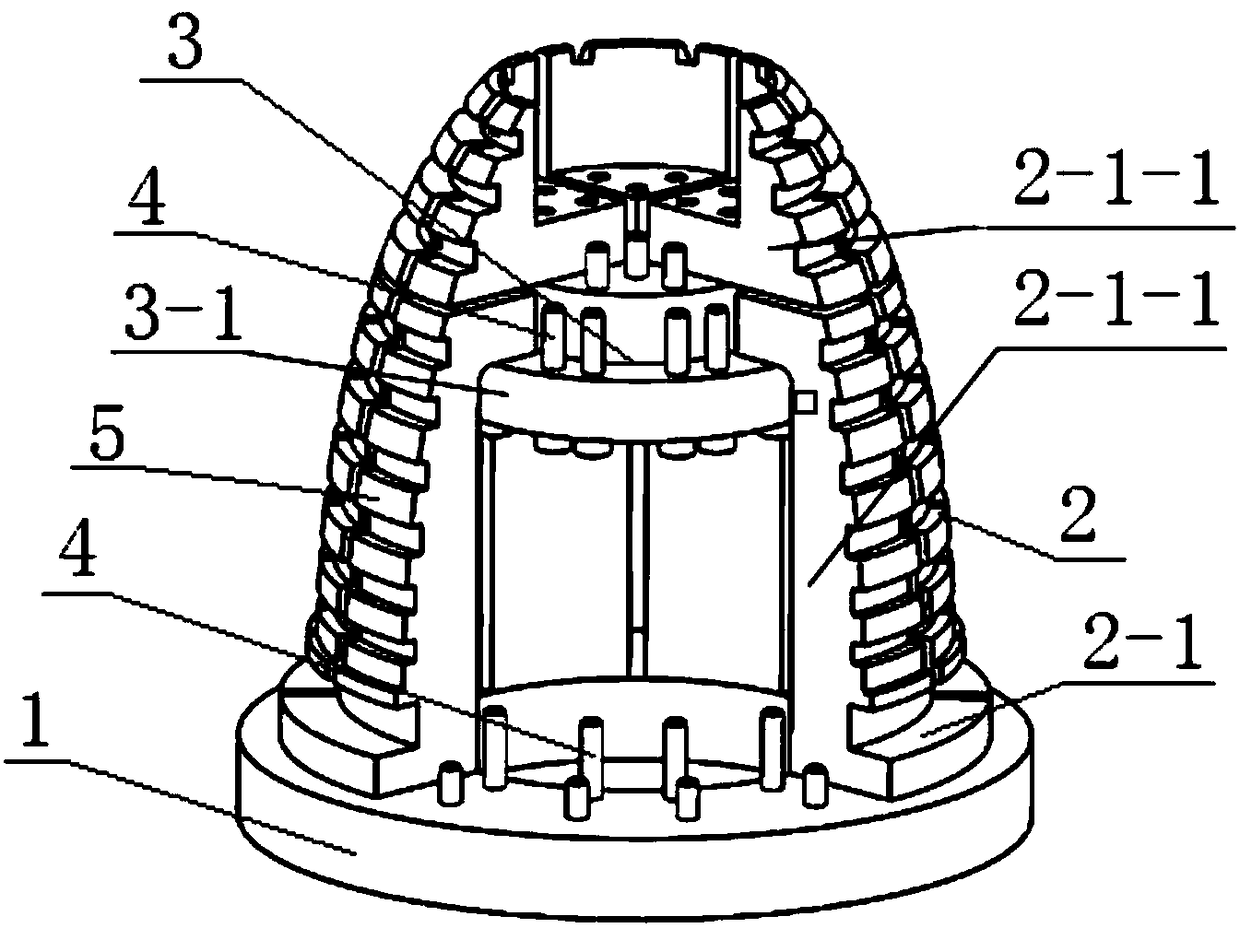
[0016] Specific implementation mode one: combine figure 1 This embodiment is described. A clamping device for high-steep conformal hood surface processing described in this embodiment includes a clamp base 1, a positioning assembly 2 and a fixing mechanism 3, and the positioning assembly 2 is fixed on the bottom of the clamp base 1. On the upper end face, the outer wall of the positioning assembly 2 is evenly arranged with a plurality of curved bosses 5 along the axial direction, each curved boss 5 is arranged along the outer circumferential direction, and the curve equation formed by the outer surface of the curved boss 5 is the same The curve equations of the inner surface of the hood are the same, and the positioning assembly 2 includes a plurality of clamp bases 2-1, and the multiple clamp bases 2-1 are evenly distributed along the circumferential direction to form a conical positioning assembly 2, and two adjacent clamp bases 2-1 There is a gap between 1, and a plurality ...

specific Embodiment approach 2

[0018] Specific implementation mode two: combination figure 1 Describe this embodiment, the jig base 2-1 in this embodiment includes a plurality of base blocks 2-1-1, the base blocks 2-1-1 are arranged in sequence from bottom to top, and two adjacent base blocks 2-1 There is a gap between -1, and the curved surface boss 5 is arranged on the outer surface of the base block 2-1-1. The undisclosed technical features in this embodiment are the same as those in the first embodiment.

[0019] Such a design further optimizes the size and structure of the positioning component 2 with the goal of reducing the mass on the premise of ensuring the rigidity of the positioning component 2, so as to further reduce the influence of the material expansion of the positioning component 2 due to heating and temperature rise during disassembly.

specific Embodiment approach 3

[0020] Specific implementation mode three: combination figure 1 To illustrate this embodiment, the fixing mechanism 3 in this embodiment includes a plurality of fixed discs 3-1, and the plurality of fixed discs 3-1 are arranged horizontally from top to bottom, and the outer diameter of the fixed discs 3-1 is from top to bottom. Incrementing from bottom to bottom, the inner sides of the plurality of base blocks 2-1-1 are fixedly connected to the fixed discs 3-1 respectively. The undisclosed technical features in this embodiment are the same as those in the second embodiment.

[0021] Such a design realizes effective positioning between multiple base blocks 2-1-1, making it form a complete positioning assembly 2.


PUM


Abstract

The invention relates to the technical field of machining clamping devices, in particular to a clamping device and method for surface machining of a high-gradient conformal bow cap. The clamping device and method for surface machining of the high-gradient conformal bow cap aim to solve the problems of difficult precision safety clamping and difficult detachment after conventional machining during outer surface machining of the high-gradient conformal bow cap at present. The clamping device comprises a clamp base, a positioning component and a fixing mechanism, wherein the positioning component is fixedly connected to the upper end surface of the clamp base; a plurality of curved lug bosses are uniformly distributed on the outer side wall of the positioning component in the axial direction; each curved lug boss is arranged in the outer circumferential direction; a curvilinear equation formed by the outer surfaces of the curved lug bosses is the same as that of the inner surface of the bow cap; and the positioning component comprises a plurality of clamp base bodies which are uniformly distributed in the circumferential direction to form the conical positioning component and are fixedly connected through the fixing mechanism. The clamping method comprises the following steps of painting of low-stress glue; bonding molding; dismounting of the clamping device; and removal of the bow cap. The clamping device and the clamping method are used for surface machining of the bow cap.

Description

technical field [0001] The invention relates to a clamping device and a clamping method for surface processing of a high-steep conformal hood. Background technique [0002] In order to adapt to the development of high-speed aircraft and balance the aerodynamic requirements of the aircraft, the contradiction between stealth and optical performance, conformal optical components came into being, that is, to smoothly adapt to the external shape of the system platform for the purpose of improving the aerodynamic performance of the system optical window. The primary key element in the application of conformal optical components is the aircraft's hood. Compared with the traditional hemispherical hood, the high-steep conformal hood can significantly reduce the flight resistance of the aircraft, improve the air flow field around the aircraft, and reduce the Effects of small aero-optical effects on image quality inside aircraft. [0003] Compared with the traditional hemispherical h...

Claims


Application Information

Patent Timeline
Patent Type & Authority Patents(China)
IPC IPC(8): B23Q3/00
CPCB23Q3/00B23Q2703/10
Inventor 郭兵张春雨王金虎赵清亮高志浩刘晗
Owner HARBIN INST OF TECH
Why Eureka
Try Eureka