


Quick Research
Generate reliable direction feasibility study reports for your R&D in just a few steps.

Technical Q&A
Discover and master advanced knowledge NOW. Basics, ideas, possibilities, all at once.

Find Solutions
As an expert in R&D theories, this can generate solutions to your technical problems instantly.

Evaluate Feasibility
Analyze your overall solution with one click, know your potential R&D risks in advance.

Monitor Landscape
Get weekly tech updates, stay abreast of the latest tech innovations and key insights.
Clamping device and clamping method for concave processing of large aspect ratio aspheric optical element
A technology of optical components and large aspect ratio, applied in optical components, optics, installation, etc., can solve problems such as difficult disassembly, and achieve the effect of improving safety, improving processing accuracy, and safe and reliable disassembly
- Summary
- Abstract
- Description
- Claims
- Application Information
AI Technical Summary
Problems solved by technology
Method used
Image

Examples
specific Embodiment approach 1
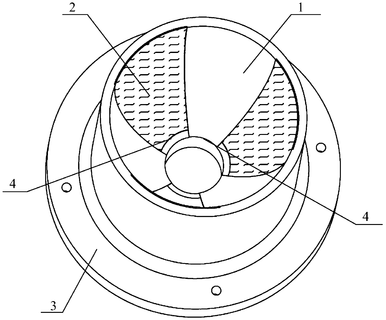
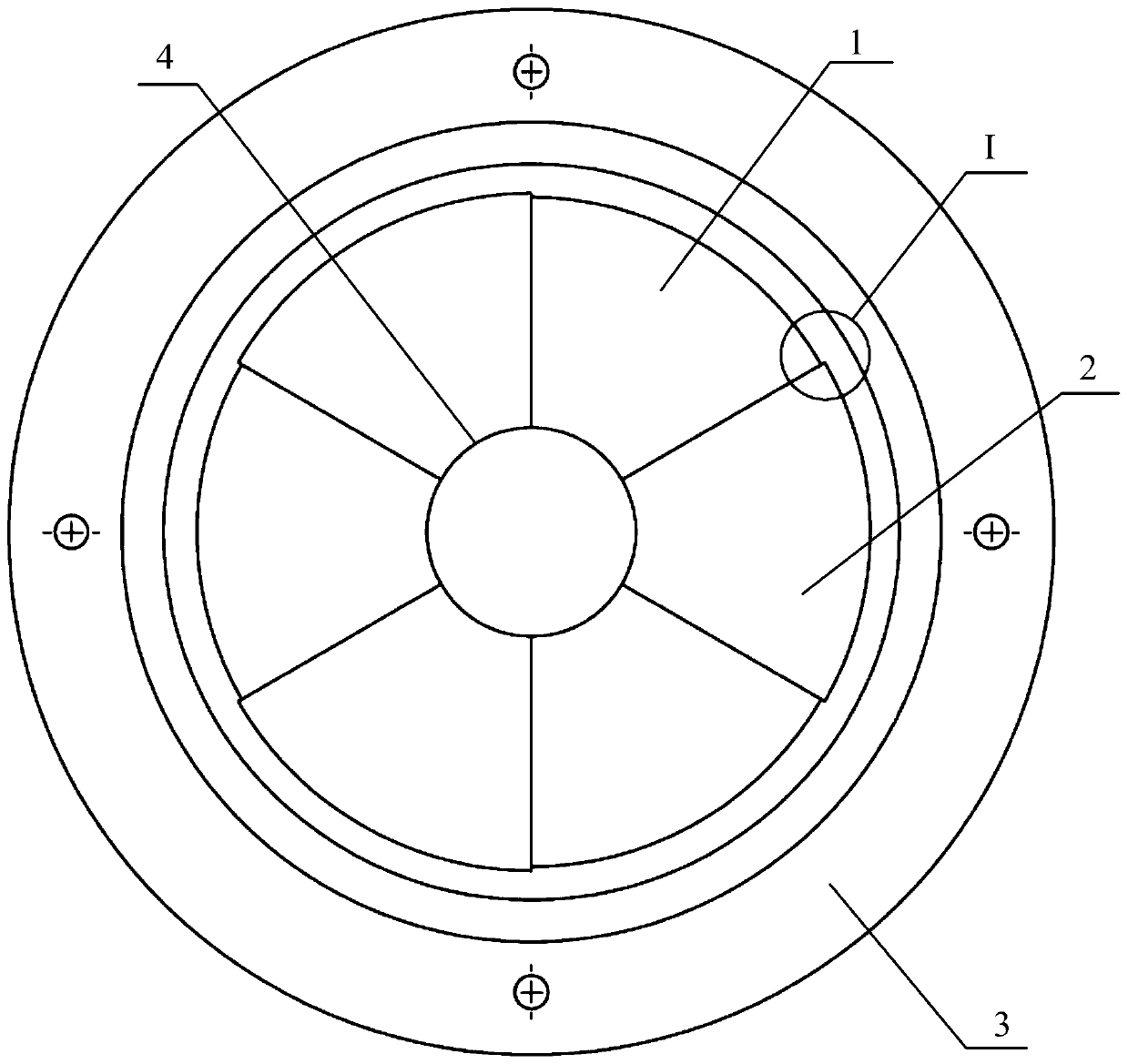
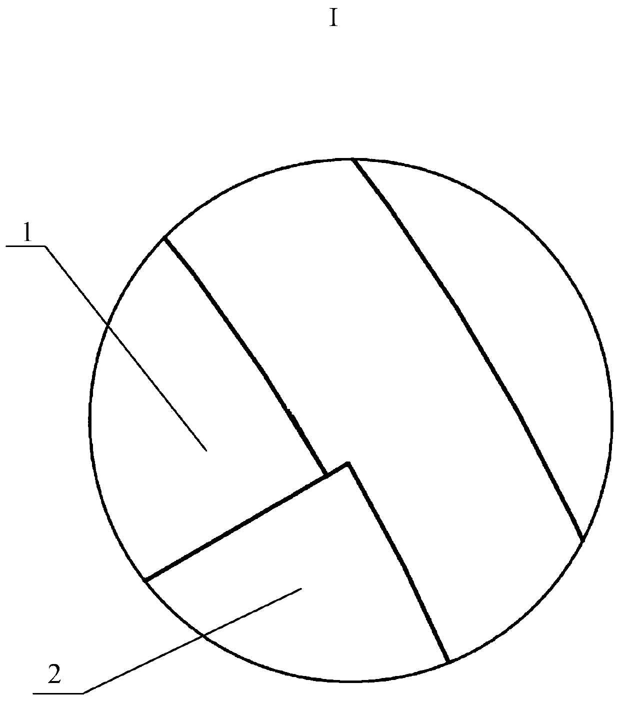
[0019] Specific implementation mode one: combine Figure 1 to Figure 4 This embodiment is described. The clamping device for concave processing of large aspect ratio aspheric optical elements in this embodiment includes a fixture base 3, multiple positioning bases 1 and multiple bonding bases 2, multiple positioning bases 1 and multiple The bonding matrix 2 is arranged alternately on the upper end surface of the fixture base 3 along the circumferential direction, the inner side walls of the positioning matrix 1 and the bonding matrix 2 are both curved surfaces, and the curve equation formed by the inner side wall of the positioning matrix 1 and the aspheric surface with a large aspect ratio The curve equations of the outer surface of the optical element are the same, and the horizontal radial dimension of the curved surface of the inner wall of the bonding base 2 is larger than the horizontal radial dimension of the curved surface of the inner wall of the positioning base 1 at ...
specific Embodiment approach 2
[0021] Specific implementation mode two: combination Figure 1 to Figure 4 Describe this embodiment, the positioning substrate 1 described in this embodiment is a positioning substrate made of polymethyl methacrylate, the bonding substrate 2 is a bonding substrate made of polymethyl methacrylate, and the clamp base 3 is polymethacrylic acid Clamp base made of methyl ester. The undisclosed technical features in this embodiment are the same as those in the first embodiment.
[0022] The material of the clamping device is polymethyl methacrylate. The abbreviation code of polymethyl methacrylate is PMMA, commonly known as plexiglass. It is half of ordinary glass, but its anti-fragmentation ability is several times higher. It has good insulation and mechanical strength and is easy to process. PMMA is currently the best polymer transparent material, with an optical transmittance of 92%. The PMMA material of the clamping device is easy to be turned and processed with high precision...
specific Embodiment approach 3
[0023] Specific implementation mode three: combination Figure 1 to Figure 4 This embodiment will be described. The lower end surfaces of the positioning base 1 and the bonding base 2 described in this embodiment are fixedly connected to the upper end surface of the fixture base 3 . The undisclosed technical features in this embodiment are the same as those in the first or second specific embodiment.
PUM
 Abstract
Description
Claims
Application Information
 - R&D Engineer
- R&D Manager
- IP Professional
- Industry Leading Data Capabilities
- Powerful AI technology
- Patent DNA Extraction
Browse by: Latest US Patents, China's latest patents, Technical Efficacy Thesaurus, Application Domain, Technology Topic, Popular Technical Reports.
© 2024 PatSnap. All rights reserved.Legal|Privacy policy|Modern Slavery Act Transparency Statement|Sitemap|About US| Contact US: help@patsnap.com