Cold forging punch

A punching and cold forging technology, applied in forging presses, forging presses, forging/pressing/hammer devices, etc., can solve the problems of insufficient pressure and high energy consumption, improve manufacturing accuracy, ensure high precision forging and high rigidity performance Effect

Active Publication Date: 2019-01-11
TONGXIANG KAISHENG PRECISION MACHINERY
View PDF1 Cites 0 Cited by
  • Summary
  • Abstract
  • Description
  • Claims
  • Application Information

AI Technical Summary

Problems solved by technology

This solution cannot solve the above problems very well, the energy consumption is still very large, and the pressure is insufficient

Method used


Image

  • Cold forging punch
  • Cold forging punch
  • Cold forging punch

Examples


Embodiment Construction

[0029] The present invention will be further described in detail below in conjunction with the accompanying drawings and examples. The following examples are explanations of the present invention and the present invention is not limited to the following examples. In this embodiment, existing technologies can be used for specific development parts, so further details will not be described in this specification.

[0030] Example.

[0031] see Figure 1 to Figure 7 .

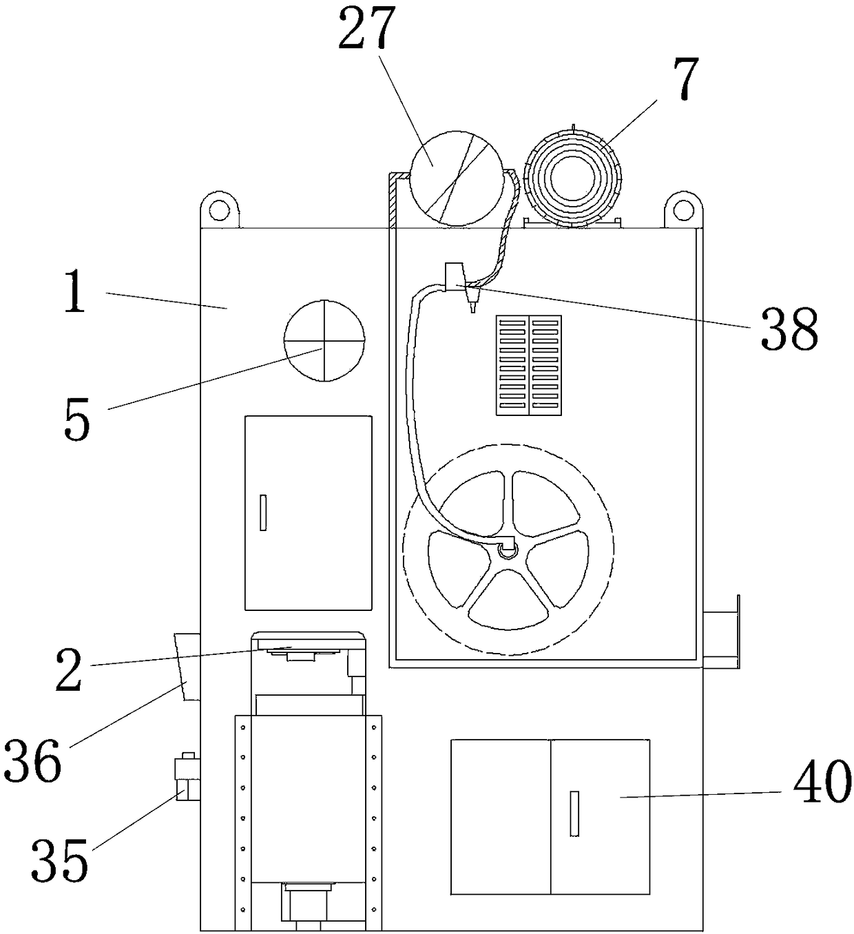
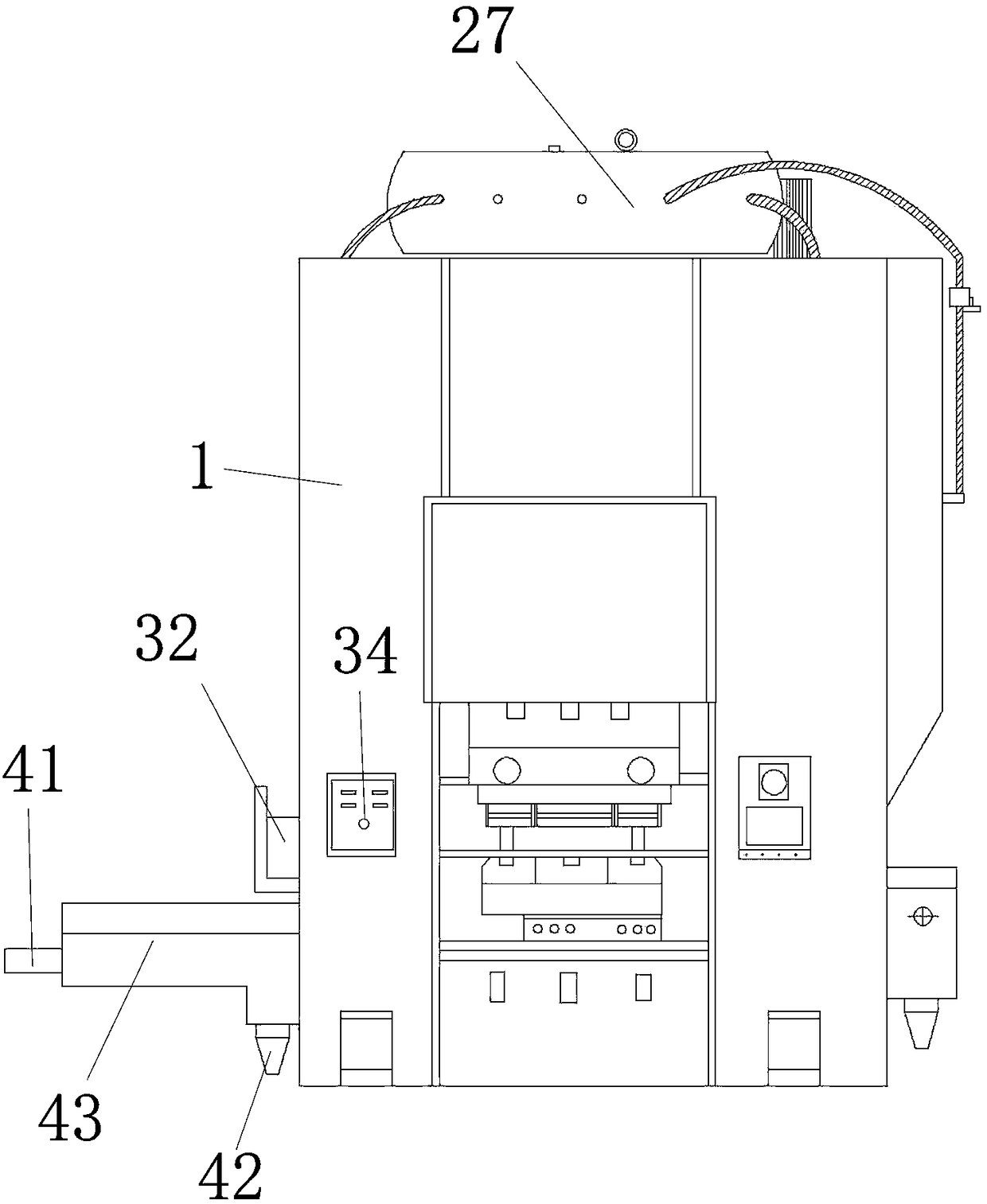
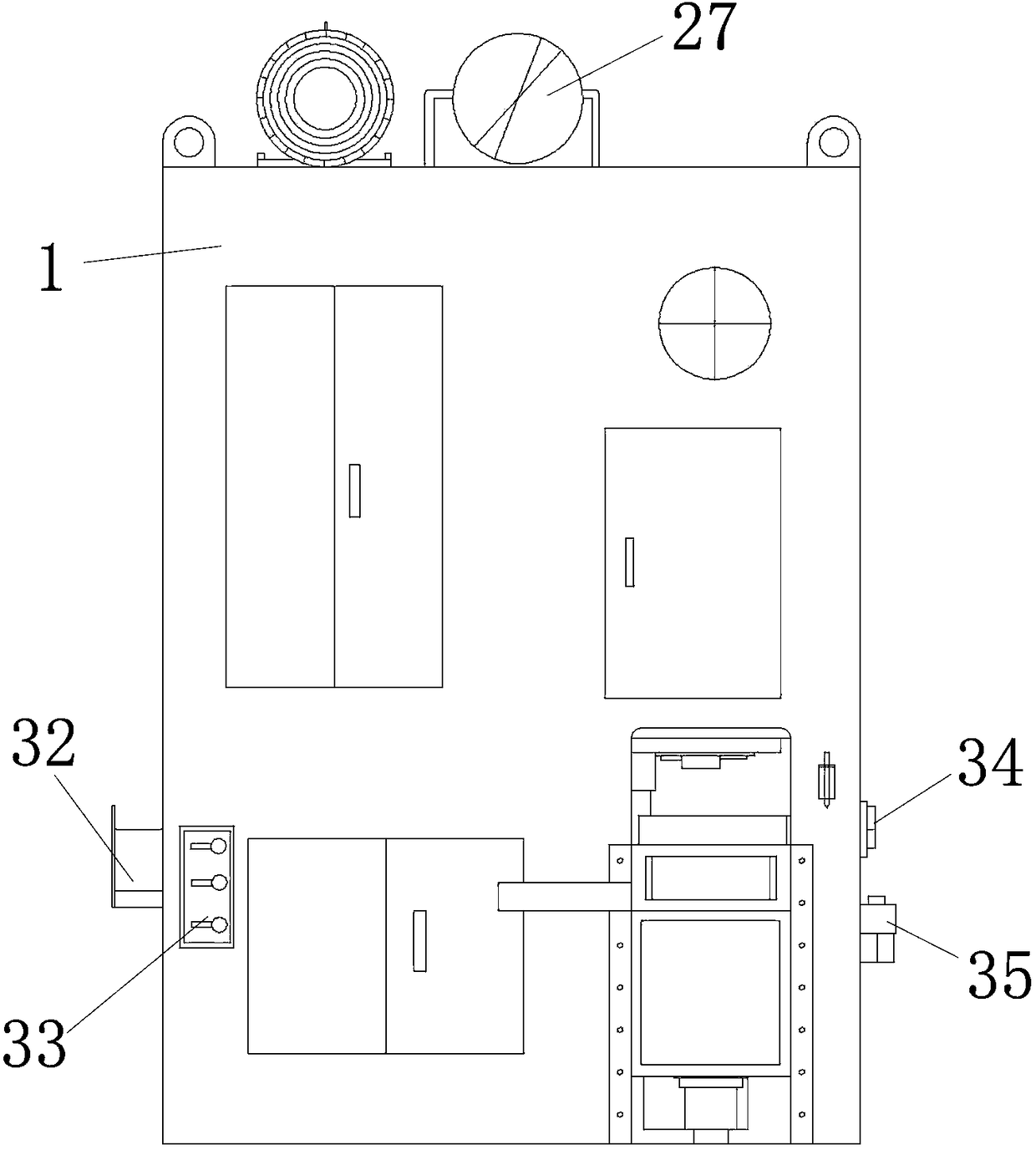
[0032] This embodiment is a toggle-type punch press, specifically a toggle-type cold forging punch press. The prior art is a common crankshaft punch press. The cold forging press of this embodiment includes a bed 1 and a drive mechanism, and the drive mechanism includes a slider 2, a gear mechanism, an upper toggle 3, a lower toggle 4, a main drive shaft 5, a clutch, a brake 6, and a slider adjustment device.

[0033] Bed 1 is a cuboid, and the interior of bed 1 is divided into bed front, bed rear, bed left and b...


PUM


Abstract

The invention relates to a cold forging punching machine. The cold forging punching machine comprises a machine body and a driving mechanism; the driving mechanism comprises a slide block; the driving mechanism comprises a gear mechanism, an upper elbow joint, a lower elbow joint, a main transmission shaft, a clutch, a brake and a slide block adjusting device; the gear mechanism comprises a main motor, a large gear, a small gear, a flywheel, a V-shaped belt, an eccentric wheel and an active connecting rod; the main motor and the flywheel are connected through a V-shaped belt; the small gear and the flywheel have the same center shaft; the small gear is engaged with the large gear; the diameter of the small gear is larger than the diameter of the large gear; the eccentric wheel is arranged on the large gear; the diameter of the eccentric wheel is smaller than the diameter of the large gear; and the active connecting rod comprises an active connecting rod large end and an active connecting rod small end. The cold forging punching machine is lower in energy consumption, high in pressure and high in precision.

Description

technical field [0001] The invention relates to a cold forging punch, which belongs to the field of machinery. Background technique [0002] Cold forging is a processing method with low energy consumption and high precision. In the prior art, cold forging requires relatively high pressure and high energy consumption. [0003] Chinese patent 201610035207.1 discloses a cold forging tool, including a work table and a top plate, at least two support beams are fixed between the top plate and the work table, a motor is provided at the lower end of the top plate, and a telescopic column is connected to the lower end of the motor, and the lower part of the telescopic column An upper workbench is fixed, and a fixed column is fixed in the middle of the bottom surface of the upper workbench. The lower end of the fixed column is connected with a lower pressure column. column, a fixed table is fixed on the work table, a lower work table is fixed on the fixed table, a shell is fixed on ...

Claims


Application Information

Patent Timeline
Patent Type & Authority Patents(China)
IPC IPC(8): B21J9/02B21J9/18B21J9/20B21J13/00B21J13/14B30B15/04B30B15/10B30B15/12
CPCB21J9/02B21J9/18B21J9/20B21J13/00B21J13/14B30B15/04B30B15/10B30B15/12
Inventor 沈一中
Owner TONGXIANG KAISHENG PRECISION MACHINERY
Why Eureka
Try Eureka