
Laminating apparatus and laminating method for curved surface screen

A technology of bonding devices and curved screens, which is used in projection devices, magnetic materials, photovoltaic power generation, etc.

Active Publication Date: 2017-07-04
WUHAN CHINA STAR OPTOELECTRONICS TECH CO LTD
View PDF6 Cites 47 Cited by
  • Summary
  • Abstract
  • Description
  • Claims
  • Application Information

AI Technical Summary

Problems solved by technology

[0005] The invention provides a curved screen bonding device and a bonding method thereof, which can realize the bonding of curved screens with relatively large curvatures, so as to solve the problem that the existing bonding devices can only bond OLED panels with relatively small curvatures. , when the curved surface design at both ends of the OLED panel tends to bend inward, the existing bonding device cannot be used to achieve the technical problem of bonding

Method used


Image

  • Laminating apparatus and laminating method for curved surface screen
  • Laminating apparatus and laminating method for curved surface screen
  • Laminating apparatus and laminating method for curved surface screen

Examples


Embodiment Construction

[0033] The following descriptions of the various embodiments refer to the accompanying drawings to illustrate specific embodiments in which the invention may be practiced. The directional terms mentioned in the present invention, such as [top], [bottom], [front], [back], [left], [right], [inside], [outside], [side], etc., are only for reference The orientation of the attached schema. Therefore, the directional terms used are used to illustrate and understand the present invention, but not to limit the present invention. In the figures, structurally similar elements are denoted by the same reference numerals.

[0034] The present invention is aimed at the curved screen bonding device of the prior art, which can only realize the bonding of OLED panels with a small curvature. When the curved surface design at both ends of the OLED panel tends to bend inward, the existing bonding device cannot There is a technical problem of device bonding; this embodiment can solve this defect....


PUM


Abstract

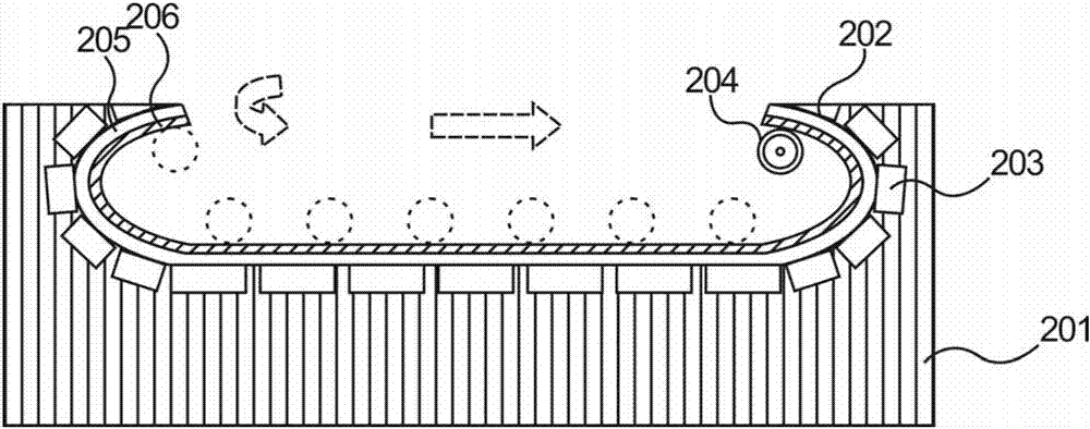
The invention provides a laminating apparatus for a curved surface screen. The laminating apparatus is used for realizing lamination of a flexible display layer and a curved surface cover plate. The laminating apparatus comprises a base platform, a magnetic layer, an attachment roll shaft and a controller, wherein a cambered surface is formed on the upper surface of the base platform; the magnetic layer is arranged on all regions at the bottom of the cambered surface; the magnetic layer comprises a plurality of mutually-independent strip-shaped magnetic field generators; the attachment roll shaft is adsorbed on the cambered surface to move to perform rolling pressing and shaping on the flexible display layer; and the controller controls the strip-shaped magnetic field generators to be started and closed independently so as to form a mobile magnetic field to guide the attachment roll shaft to move. The laminating apparatus has the beneficial effects as follows: compared with the existing laminating apparatus for the curved surface screen, the laminating apparatus for the curved surface screen disclosed by the invention can realize lamination between an OLED panel with relatively high curvature and a curved surface glass cover plate, so that the problem that the laminating apparatus in the prior art can only realize lamination of the OLED panel with relatively low curvature, and the problem that lamination of the OLED panel cannot be realized when the curved surfaces at the two ends of the OLED panel are bent towards the interior of the panel are solved.

Description

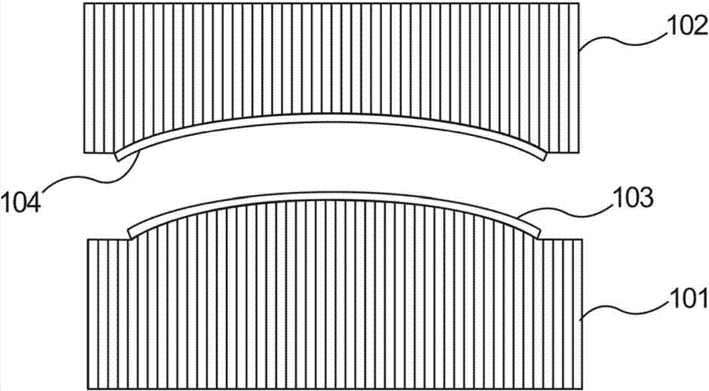
technical field [0001] The invention relates to display screen bonding equipment, in particular to a curved screen bonding device and a bonding method thereof. Background technique [0002] The LCD (Liquid Crystal Display, Liquid Crystal Display) industry has entered a mature stage. Flexible OLED (Organic Light-Emitting Diode, Organic Light-Emitting Diode) displays are a new growth point for the future display industry. The flexible characteristics of flexible OLED displays are constantly being developed and utilized. , such as attaching the flexible OLED to the curved glass cover can realize the front and side display of the product. [0003] Such as figure 1 As shown, the current 3D bonding method for flexible OLED panels is: 1) provide a lower fixing module 101, the upper part of the lower fixing module 101 is formed with an arc-shaped convex surface, and an upper fixing module 102 is provided, and the lower part of the upper fixing module 102 is formed with an arc The ...

Claims


Application Information

Patent Timeline
Patent Type & Authority Applications(China)
IPC IPC(8): H01L27/32H01L51/52H01L51/56H10K99/00
CPCH10K59/87Y02E10/549H10K77/111H01F1/117G06F1/1652G06F1/1601G03B21/58G06F1/1616H10K50/84H10K2102/311
Inventor 王剑波
Owner WUHAN CHINA STAR OPTOELECTRONICS TECH CO LTD
Learn More