
A method for measuring local surface resistance of polluted insulators

A technology of surface resistance and measurement method, applied in the direction of measurement device, measurement of electrical variables, measurement of resistance/reactance/impedance, etc., can solve problems such as affecting measurement accuracy, and achieve the effect of eliminating contact resistance, reliable and real pollution, and simple operation.

Active Publication Date: 2019-10-11
BEIJING GUODIAN FUTONG SCI & TECH DEV
View PDF7 Cites 0 Cited by
  • Summary
  • Abstract
  • Description
  • Claims
  • Application Information

AI Technical Summary

Problems solved by technology

At present, a lot of data have been accumulated, but the equivalent salt density method is difficult to directly reflect the impact of pollution on the insulation of insulators, which is very important for the operation of insulators and other equipment
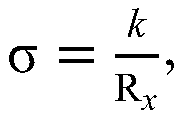
[0004] The local conductivity method is another method to measure the pollution degree of insulators. Since there is a certain relationship between the local surface conductivity and the equivalent salt density Sa in theory, it can be more accurate by measuring the local conductivity of polluted insulators. Reflect the pollution status of insulators, such as "Local Surface Conductivity-A New Method to Characterize the Pollution Degree of Insulators" published in the journal "High Voltage Technology" in 1990, but according to its measurement method, the surface conductivity of polluted insulators It is obtained by measuring with a measuring probe, and the introduction of the probe inevitably introduces the corresponding contact resistance, and the area of ​​the probe is small, which will affect the measurement accuracy due to the conductivity characteristics of the moist medium itself

Method used


Image

  • A method for measuring local surface resistance of polluted insulators
  • A method for measuring local surface resistance of polluted insulators
  • A method for measuring local surface resistance of polluted insulators

Examples


Embodiment 1

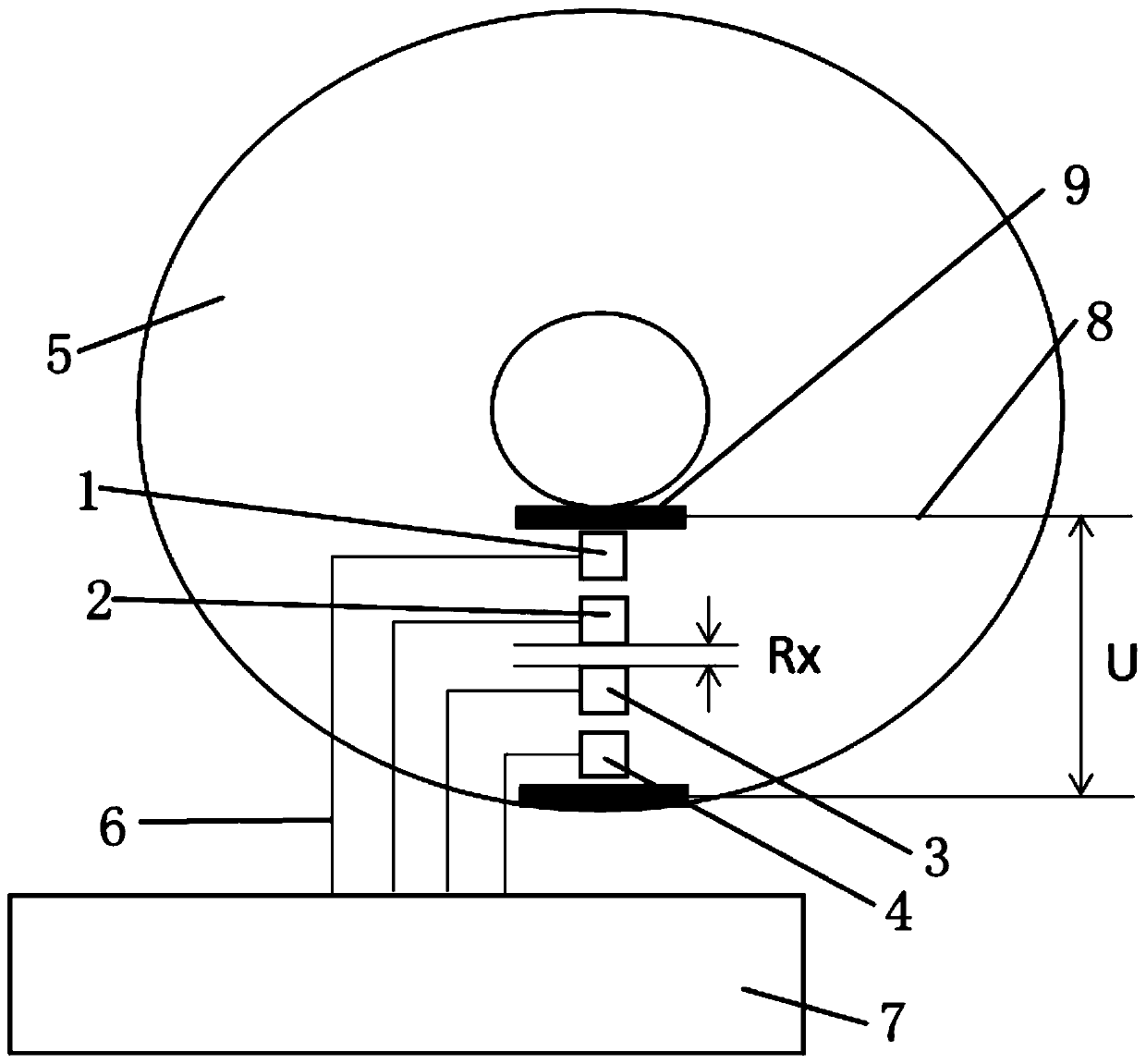
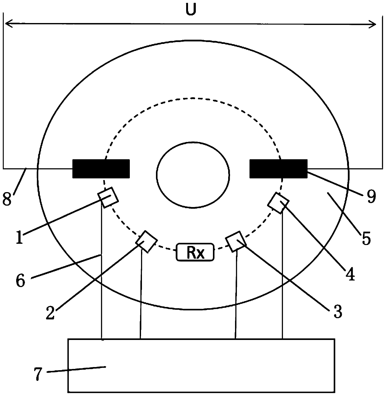
[0039] The sticking area of ​​the aluminum foil tapes 1, 2, 3, 4 on the polluted insulator 5 to be tested is an arc edge with the same radius from the center of the polluted insulator 5 to be tested.

Embodiment 2

[0041] The sticking area of ​​the aluminum foil tapes 1, 2, 3, 4 on the polluted insulator 5 to be tested is a diameter at the center of the polluted insulator 5 to be tested.

[0042] In the above two embodiments, the partial division methods of the aluminum foil tapes 1, 2, 3, and 4 to the polluted insulator under test can ensure the stability of the current flow when the overall pressure is applied to the polluted insulator under test.

[0043] In the above-mentioned embodiment 1, when a voltage is applied to the polluted insulator 5 as a whole, the two ends of the applied voltage should preferably be the same arc edges pasted on the insulator 5 by the aluminum foil tape 1, 2, 3, and 4, so as to ensure the continuity of the current. shortest path.

[0044] In the above-mentioned embodiment 2, when a voltage is applied to the measured dirty insulator 5 as a whole, the two ends of the applied voltage should preferably be the two ends of the same diameter pasted on the tested in...


PUM


Abstract

The present invention discloses a measurement method for local surface resistance of a contaminated insulator, belonging to the insulator contamination detection technology field. The measurement method comprises: the step 1: fixing a measured contaminated insulator on a sample frame, and employing a plurality of aluminum tapes with the same size to perform local segmentation of the measured contaminated insulator; the step 2: employing copper wires to connect all the aluminum tapes with a resistance measuring meter, applying voltage to the whole measured contaminated insulator, and employing the resistance measuring meter to measure and obtain resistance values of different wires; and the step 3: employing an area resistance value superposition method to calculate and obtain the surface resistance of the corresponding area of the measured contaminated insulator. The measurement method for local surface resistance of the contaminated insulator can reliably reflect the real pollution condition of the insulator surface and is simple to operate.

Description

technical field [0001] The invention relates to the technical field of insulator pollution detection, in particular to a method for measuring the local surface resistance of polluted insulators. Background technique [0002] The outdoor electrical equipment of transmission lines and substations, especially the insulators commonly used in overhead lines, are often polluted by industrial pollution or natural salinity, flying dust, bird droppings, etc. When the relative humidity is low, the resistance of the pollution layer is very large, and the insulation performance will not be reduced. However, under high relative humidity, such as fog, dew, light rain, snow and other adverse weather conditions, the electrolyte in the pollution layer will be damp and dissolved, making the surface of the insulator The conductivity increases, the insulation performance decreases, and the non-electrolyte in the dirty layer can retain moisture, which promotes the further moisture of the dirty l...

Claims


Application Information

Patent Timeline
Patent Type & Authority Patents(China)
IPC IPC(8): G01R27/08
Inventor 王建辉赵悦菊耿刚强王国刚滕济林张亚明张培林苗文华穆静静刘金龙吴刘锁郑永立卢明刘泽辉
Owner BEIJING GUODIAN FUTONG SCI & TECH DEV
Learn More