
Six-dimensional force sensor

A six-dimensional force sensor and sensor technology, applied in instruments, measuring force components, measuring fluid pressure, etc., can solve problems such as high coupling degree of component force, high precision requirements of parts, and small Z-direction bearing load, etc., to achieve inter-dimensional The effect of low coupling degree, low precision requirement and low processing cost

Active Publication Date: 2017-07-04
SOUTHEAST UNIV
View PDF10 Cites 14 Cited by
  • Summary
  • Abstract
  • Description
  • Claims
  • Application Information

AI Technical Summary

Problems solved by technology

Using the principle of sensor measurement, the six-dimensional force sensor mainly consists of capacitive, piezoresistive, strain, and piezoelectric. Low, capacitive and piezoelectric sensors have the disadvantage of small range
Chinese patent CN201310479891.9 uses double-layer cross beams to achieve decoupling, and discloses an orthogonal decoupling six-dimensional force sensor, which has the disadvantages of large z-direction size, small z-direction load and high processing cost. Chinese patent CN201620008204 .4 discloses a compact six-dimensional force sensor, which is only suitable for small-scale application scenarios
Chinese patent CN201420298602.5 achieves force decoupling through a biaxial elastic hinge, which has the disadvantages of non-dual orthogonality, uneven application of force, and inaccurate measurement
Chinese patent CN201310533609.0 adopts an integrated processing method to design the cross beam, and uses pin shafts to set the matching accuracy of multiple matching parts to achieve overload protection, which has the disadvantages of high precision requirements for each part and high processing costs.

Method used


Image

  • Six-dimensional force sensor
  • Six-dimensional force sensor
  • Six-dimensional force sensor

Examples


Embodiment Construction

[0030] The technical solution of the present invention will be further described in detail below in conjunction with the embodiments and the accompanying drawings.

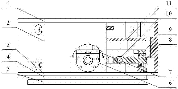
[0031] Such as figure 1 and figure 2 As shown, a six-dimensional force sensor with overload protection of the present invention includes an upper end cover 1, a housing 2, a sensor base 3, a rubber sealing ring 4, an overload protection mounting plate 5, a bearing end cover 6, and a bearing block 7 , elastic body 8, bearing 9, strain gauge 10, acquisition circuit board 11. Among them, the elastic body 8 is used to measure the three component forces F in the space coordinate system x , F y , F z and three moments M x ,M y ,M z . The upper end cover 1 and the sensor base 3 are parallel to each other and fixedly connected to two ends of the shell 2 respectively. The bearing end cover 6 and the bearing block 7 are fixedly connected to the sensor base 3 by bolts respectively, and the bearing 9 is fixed on the...


PUM


Abstract

The present invention discloses a six-dimensional force sensor. The sensor comprises a sensor pedestal and a housing arranged on the sensor pedestal, and the sensor pedestal is provided with an elastomer. The elastomer is a rood beam, the rood beam comprises a center matrix and four cantilever beams connected on the center matrix, the sensor pedestal is provided with four positioning parts sliding along the axial direction, the tail end of each cantilever beam sleeves the four positioning parts sliding along the axial direction and slides along the axial direction of the positioning parts, each cantilever beam is provided with a first stress concentration position where stress concentration is generated in the horizontal plane and a second stress concentration position where stress concentration is generated in the vertical plane, strain gages configured to measure the size of the stress at the stress concentration position are respectively arranged at the first stress concentration position and the second stress concentration position. The sensor is simple and compact in structure and high in modularization to realize force decoupling, is accurate in measurement and has an overload protection effect.

Description

technical field [0001] The invention belongs to the field of sensors, in particular to a six-dimensional force sensor, and is especially suitable for the field of industrial automatic grinding. Background technique [0002] At present, most of the grinding work is manual. Manual grinding has problems such as high processing costs, endangering the health of workers, and great potential safety hazards. The more critical problem is that because of the complex shape of the workpiece, such as glass molds, castings, jade handicrafts, etc., manual grinding wastes man-hours, low processing efficiency, and low grinding output. The use of robot grinding has the advantages of high flexibility, high safety, and strong stability, and can realize the grinding work of large quantities of workpieces with complex geometric shapes. Breaking the traditional wheel hub grinding processing mode, integrating robot technology, control technology, sensor technology and other technologies, adopting ...

Claims


Application Information

Patent Timeline
IPC IPC(8): G01L5/16G01L19/06
CPCG01L5/16G01L19/0618
Inventor 王兴松任晨曦武琦琦
Owner SOUTHEAST UNIV
Learn More