Main force-bearing structure for lightweight carbon fiber reinforced resin composite stiffened plate shell

A technology for reinforcing resin and composite materials, applied in the aerospace field, can solve the problems of poor installation adaptability, poor utilization of equipment installation space, poor high temperature resistance of honeycomb sandwich shells, and high weight cost of metal reinforced shells, so as to increase the weight cost. , Improve the stability and bearing capacity, reduce the weight of the structure

Active Publication Date: 2017-07-04
BEIJING INST OF SPACECRAFT SYST ENG
View PDF5 Cites 4 Cited by
  • Summary
  • Abstract
  • Description
  • Claims
  • Application Information

AI Technical Summary

Problems solved by technology

The central load-bearing tube structure is conducive to ensuring the structural strength and rigidity, but it has poor adaptability to equipment installation and utilization of equipment installation space; the bar system structure has good adaptability to equipment installation, but the load-bearing and structural rigidity are relatively poor; box-plate structure It can provide more equipment mounting surfaces, but it needs to provide the normal bearing capacity of the structural plate through more normal support structures; compared with the box-plate structure, the shell structure can provide better normal stiffness through the curvature of the shell, combined with strengthening Rib design improves local bearing capacity, but most of the existing shell structures are metal-reinforced shells and honeycomb sandwich shells; however, the weight of the metal-reinforced shell is high, and the honeycomb sandwich shell has the disadvantage of poor high temperature resistance

Method used


Image

  • Main force-bearing structure for lightweight carbon fiber reinforced resin composite stiffened plate shell
  • Main force-bearing structure for lightweight carbon fiber reinforced resin composite stiffened plate shell
  • Main force-bearing structure for lightweight carbon fiber reinforced resin composite stiffened plate shell

Examples


Embodiment Construction

[0042] In order to make the purpose, technical solution and advantages of the present invention clearer, the following will further describe the public implementation manners of the present invention in detail with reference to the accompanying drawings.

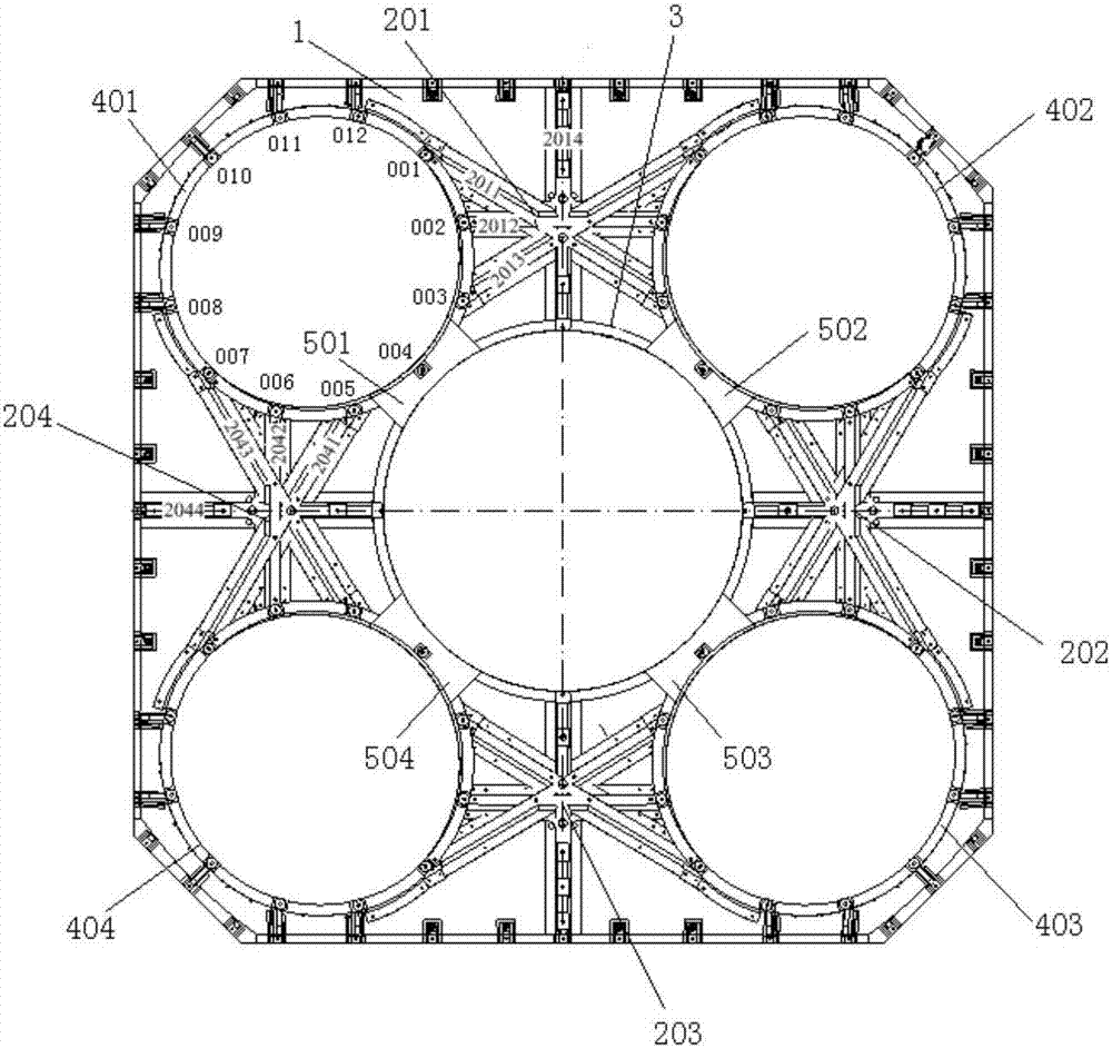
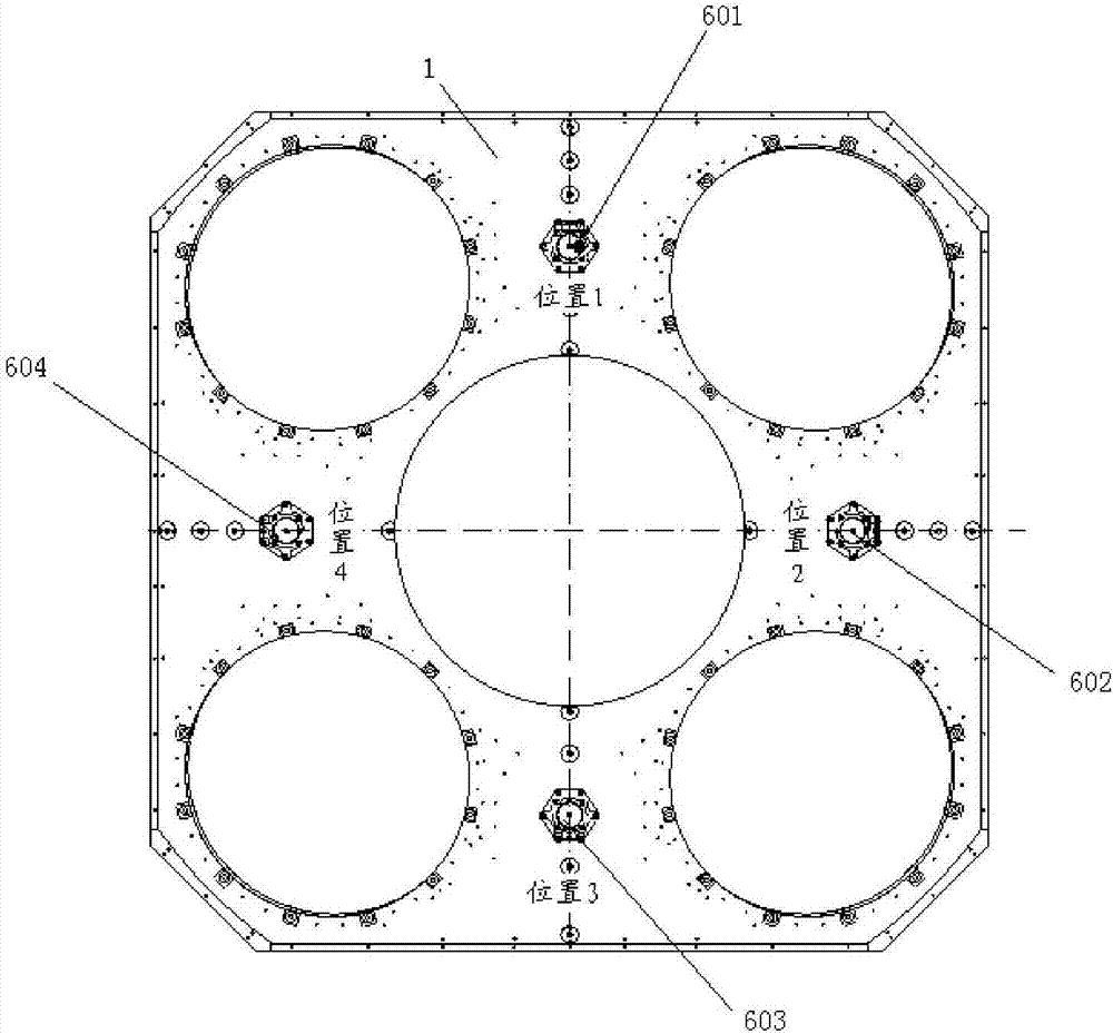
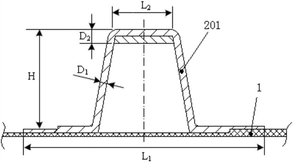
[0043] In this embodiment, the main load-bearing structure of the lightweight carbon fiber-reinforced resin composite material reinforced plate shell is designed with carbon fiber-reinforced resin material, which reduces the structural weight. The shell of the main load-bearing structure of the lightweight carbon fiber reinforced resin composite material reinforced plate shell is designed as a skin reinforced structure, and according to the actual size constraints, a suitable curvature is designed to improve the performance of the lightweight carbon fiber reinforced resin composite material. The overall normal stiffness and bearing capacity of the main load-bearing structure of the stiffened plate shell. In addition, in orde...


PUM

PropertyMeasurementUnit
The average thicknessaaaaaaaaaa

Abstract

The invention discloses a main force-bearing structure for a lightweight carbon fiber reinforced resin composite stiffened plate shell. The main force-bearing structure comprises a stressed skin, a plurality of star-shaped cap beams, a center opening C-shaped beam, a plurality of equipment mounting C-shaped beams, a plurality of reinforcing pieces and a plurality of metal reinforcing blocks, wherein the star-shaped cap beams, the center opening C-shaped beam, the equipment mounting C-shaped beams and the reinforcing pieces are arranged on one face of the stressed skin, and the metal reinforcing blocks are arranged on the other face of the stressed skin. The multiple equipment mounting C-shaped beams are evenly distributed around the center opening C-shaped beam; the center opening C-shaped beam is connected with the equipment mounting C-shaped beams through the reinforcing pieces; every two equipment mounting C-shaped beams are connected through the corresponding star-shaped cap beam; the center opening C-shaped beam and the stressed skin are connected through the star-shaped cap beams; and the star-shaped cap beams and the stressed skin form a closed cross section. According to the main force-bearing structure for the lightweight carbon fiber reinforced resin composite stiffened plate shell, the weight of the structure is reduced, and the bearing capacity and the using temperature of the structure are improved.

Description

technical field [0001] The invention belongs to the field of aerospace technology, and in particular relates to a main load-bearing structure of a lightweight carbon fiber reinforced resin composite material reinforced plate shell. Background technique [0002] The main load-bearing structure of the satellite has two main functions: (1) provide the overall configuration and provide installation support for instruments and equipment; (2) have sufficient strength to withstand the launch load and ensure the necessary rigidity and dimensional stability. The above two functions often put forward opposite design requirements for the satellite structure: in order to meet the overall configuration and facilitate the installation and support of the instrument, it is necessary to provide the largest possible installation space, ensure the best possible openness and repeated disassembly performance ; In order to ensure sufficient strength and rigidity, it is hoped that the structure is...

Claims


Application Information

Patent Timeline
IPC IPC(8): B64G1/22
CPCB64G1/22
Inventor 曾惠忠盛聪董彦芝
Owner BEIJING INST OF SPACECRAFT SYST ENG
Why Eureka
Try Eureka