
Signal transmission method, signal transmission device and signal receiving device

A signal transmission and signal technology, applied in the field of communication, can solve problems such as signal co-frequency interference, a large number of wiring resources, etc.

Active Publication Date: 2017-06-30
ADMINISTATION OF RADIO STATIONS OF STATE ADMINISTATION OF PRESS PUBLICATION RADIO FILM & TELEVISION +2
View PDF5 Cites 0 Cited by
  • Summary
  • Abstract
  • Description
  • Claims
  • Application Information

AI Technical Summary

Problems solved by technology

[0004] However, in the prior art, since the sending end needs to send 224 carrier signals and 224 module switch control signals to the RF power module of the receiving end through the connecting cable between the sending end and the receiving end, the sending end and the receiving end A large number of connecting cables are required between them, and a large amount of wiring resources are required, and due to the large amount of wiring, each carrier signal and each module switch control signal are signals of the same frequency, so that there will be interference of the same frequency between the two types of signals

Method used


Image

  • Signal transmission method, signal transmission device and signal receiving device
  • Signal transmission method, signal transmission device and signal receiving device
  • Signal transmission method, signal transmission device and signal receiving device

Examples


Embodiment Construction

[0037] In order to make the purpose, technical solutions and advantages of the embodiments of the present invention clearer, the technical solutions in the embodiments of the present invention will be clearly and completely described below in conjunction with the drawings in the embodiments of the present invention. Obviously, the described embodiments It is a part of embodiments of the present invention, but not all embodiments. Based on the embodiments of the present invention, all other embodiments obtained by persons of ordinary skill in the art without making creative efforts belong to the protection scope of the present invention.

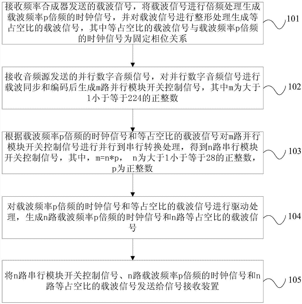
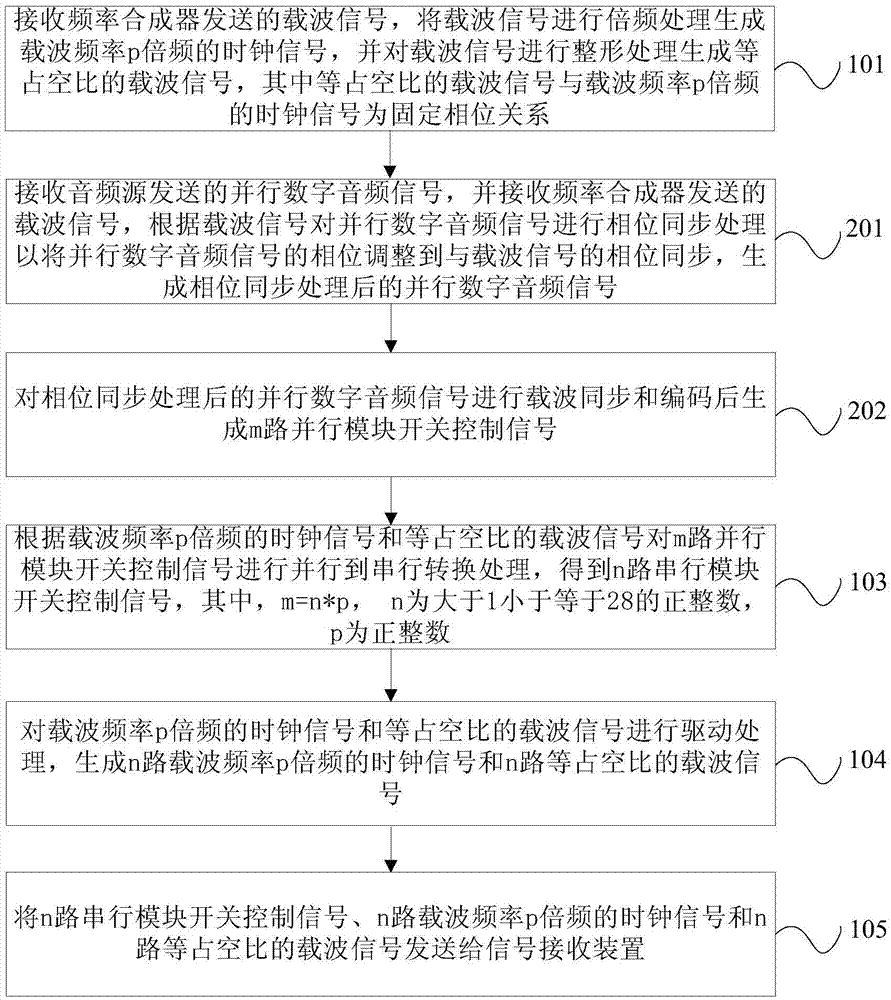
[0038] figure 1 The flow chart of the signal transmission method provided by Embodiment 1 of the present invention, such as figure 1 As shown, the method of the present embodiment includes:

[0039] Step 101, receiving the carrier signal sent by the frequency synthesizer, performing frequency multiplication processing on the carrier signal ...


PUM


Abstract

The invention provides a signal transmission method, a signal transmission device and a signal receiving device. The method comprises the steps of carrying out parallel-to-serial conversion processing on m parallel module switching control signals according to clock signals of which carrier frequency is multiplied by p and carrier signals with equal duty cycles, thereby obtaining n serial module switching control signals; carrying out drive processing on the clock signals of which carrier frequency is multiplied by p and the carrier signals with the equal duty cycles, thereby generating n clock signals of which carrier frequency is multiplied by p and n carrier signals with the equal duty cycles; and sending the n serial module switching control signals, the n clock signals of which carrier frequency is multiplied by p and the n carrier signals with the equal duty cycles to a signal receiving device, wherein the m is equal to n*p, the m is greater than 1 and is smaller than or equal to 224 and the m is a positive integer, the n is greater than 1 and is smaller than or equal to 28 and the n is the positive integer, and the p is the positive integer. A great number of wiring resources are reduced, and the same frequency interference between the carrier signals and the module switching control signals is reduced.

Description

technical field [0001] The present invention relates to communication technology, in particular to a signal transmission method, a signal sending device and a signal receiving device. Background technique [0002] Broadcasting transmitters mainly use high-power medium-wave transmitters for local coverage of medium-wave broadcasting in a large area (such as within the province). Currently, high-power medium-wave transmitters can only achieve single-frequency broadcasting due to the complexity of technical implementation. , even if the broadcasting frequency is replaced, it will require expensive renovation funds. In the operation and maintenance process of the transmitting station, in order to ensure the uninterrupted broadcasting, it is necessary to equip a spare transmitter. The way of broadcasting needs to install a spare machine for each transmitter, and the engineering investment and equipment maintenance costs are very huge. [0003] In the prior art, a multi-frequency...

Claims


Application Information

Patent Timeline
IPC IPC(8): H04B1/46H04B1/7087H04B1/7097H04L27/18H04L25/03H04L7/00
CPCH04B1/46H04B1/7087H04B1/7097H04L7/0008H04L25/03828H04L27/183
Inventor 黄晓兵徐忠张利达李国强李武银肖秋华李刘奇李晓岩王延辉徐帮辉高峰田园贾宏春刘波聂志龙王彦州高原董建丽张轩何迁曹毅郭宇航刘劲王莉孙晨张龙
Owner ADMINISTATION OF RADIO STATIONS OF STATE ADMINISTATION OF PRESS PUBLICATION RADIO FILM & TELEVISION
Learn More