Lamp bar using bent pin LED lamp declination and display screen
A technology of LED lamps and light strips, which is applied in the direction of lighting and heating equipment, parts of lighting devices, semiconductor devices of light-emitting elements, etc., and can solve the problems of LED lights falling down, installation difficulties, maintenance and replacement of faulty light strips, etc. Achieve the effect of easy manufacture and maintenance, low risk and simple structure
- Summary
- Abstract
- Description
- Claims
- Application Information
AI Technical Summary
Problems solved by technology
Method used
Image
Examples
Embodiment 1
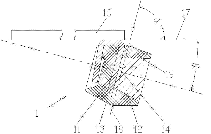
[0034] Embodiment 1 is a light bar that uses bent-leg LED lights to tilt down. Figure 7 It is a schematic diagram of the structure of Example 1 (on the lamp board). See Figure 7, the light strip PCB 2 is equipped with a straight-leg circuit connector 3, and the two rows of pins 6 at one end of the circuit connector 3 are straight-leg pins, straddling the front and back sides of the light strip PCB 2 for soldering connection. When the straight leg at the other end of the circuit connector 3 is connected to the upright PCB 10 , the light bar PCB 2 and the upright PCB 10 are perpendicular to each other. The light bar PCB 2 is also equipped with a drive control circuit. The LED lamp 1 is vertically inserted and welded on the light strip PCB 2, which can be mechanized for insertion and welding. Then bend all the LED lamps 1 on the light strip to the same direction, so that when the circuit connector 3 is connected to the column PCB 10, the light-emitting end face 4 of the LED ...
Embodiment 2
[0046] Embodiment 2 is another light bar that uses bent-leg LED lights to tilt down. Figure 12 It is the structural representation of embodiment 2. See Figure 12 , one end pin of the straight leg circuit connector 3 is welded vertically on the lamp bar PCB 2 , when the other straight leg of the circuit connector 3 is connected to the upright PCB 10 , the light bar PCB 2 and the upright PCB 10 are parallel to each other. The light bar PCB 2 is also equipped with a drive control circuit. The LED lamp 1 is vertically inserted and welded on the light strip PCB 2, which can be mechanized for insertion and welding. Then bend all the LED lamps 1 on the light strip to the same direction, so that when the circuit connector 3 is connected to the column PCB 10, the light-emitting end face 4 of the LED lamp 1 (that is, the plane perpendicular to the direction of the maximum light intensity of the LED lamp) An included angle is formed between its extension surface and the column PCB p...
Embodiment 3
[0052] Embodiment 3 is a light bar display screen that uses bent-leg LED lights to tilt down. Figure 13 It is the structural representation of embodiment 3. See Figure 13 , The light bar display is assembled by one or more light bars that use bent LED lights to tilt down. The column 11 is equipped with a power supply 12 and the column PCB 10 , the column PCB 10 is equipped with a circuit, and the light bar equipped with the light bar shell 8 is connected to the column PCB 10 through the circuit connector 3 .
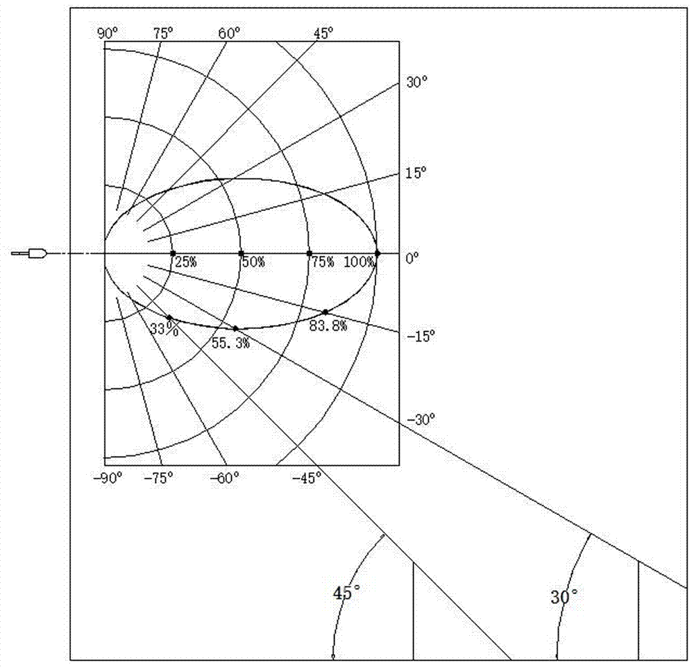
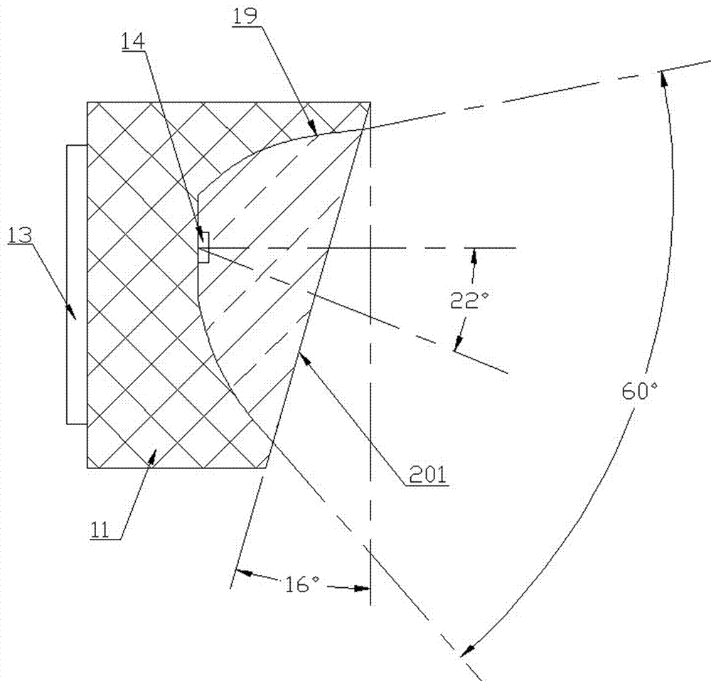
[0053] Apparently, the light bar using bent-leg LED lamps in the present invention realizes the downward inclination of the maximum light intensity angle of the LED element, improves the perception brightness of the display screen composed of it and is installed at a high place, thereby improving the brightness of the display screen. energy saving effect. For example, see figure 1 , assuming that the light distribution curves of LED lamps in Embodiments 1, 2 and 3 ...
PUM
 Abstract
Description
Claims
Application Information
 - R&D Engineer
- R&D Manager
- IP Professional
- Industry Leading Data Capabilities
- Powerful AI technology
- Patent DNA Extraction
Browse by: Latest US Patents, China's latest patents, Technical Efficacy Thesaurus, Application Domain, Technology Topic, Popular Technical Reports.
© 2024 PatSnap. All rights reserved.Legal|Privacy policy|Modern Slavery Act Transparency Statement|Sitemap|About US| Contact US: help@patsnap.com


