A led element with a dip angle, a led light bar and a display screen
A technology of components and pins, applied in the structural field of LED components, to achieve the effects of easy manufacture and maintenance, improved energy saving effect, and improved perceived brightness
- Summary
- Abstract
- Description
- Claims
- Application Information
AI Technical Summary
Problems solved by technology
Method used
Image
Examples
Embodiment 1
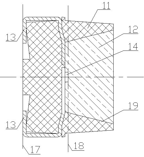
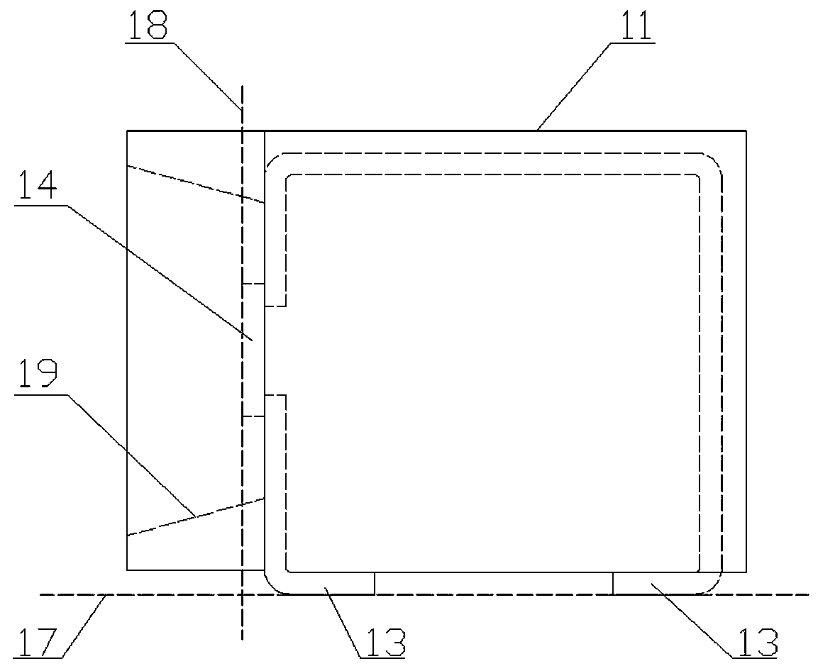
[0029] Figure 5 with Image 6 Respectively, the cross-sectional view and the front view of the structural schematic diagram of Embodiment 1. See Figure 5 with Image 6 , Embodiment 1 is a LED element 1 with an inclination angle, and its components include a plastic housing 11 with a light cup 19, a sealant 12, pins 13, an LED chip 14 and a wire 15, and the LED chip 14 connects with the wire 15 The pin 13 is connected, and the sealant 12 encapsulates a part of the LED chip 14, the wire 15 and the pin 13 in the housing 11 with the light cup 19, and the light-emitting end face 18 of the LED chip 14 (that is, the direction of the maximum light intensity of the LED chip is There is an included angle α between the plane of the normal line) and the welding plane 17 outside the LED element 1, and α is greater than 0° and less than 90°. Three LED chips that emit red, green, and blue light respectively are loaded into the LED element of Embodiment 1; as an equivalent option, other...
Embodiment 2
[0039] Figure 9 with Figure 10 Respectively, a schematic cross-sectional view of the structure of Embodiment 2 and a three-dimensional schematic view of its pins. See Figure 9 with Figure 10, Embodiment 2 is another LED element with an inclination angle, and its components include a plastic housing 11 with a light cup 19, a sealant 12, pins 13, an LED chip 14 and a wire 15, and the LED chip 14 connects with the wire 15 The pin 13 is connected, and the sealing glue 12 encapsulates the LED chip 14, the wire 15 and a part of the pin 13 in the housing 11 with the light cup 19, between the light-emitting end surface 18 of the LED chip 14 and the welding plane 17 outside the LED element Between, there is an included angle α, α is greater than 0° and less than 90°. Three LED chips that respectively emit red, green and blue light are loaded into the LED element of embodiment 2; as an equivalent option, other numbers of LED chips can also be loaded. Different from Embodiment 1...
Embodiment 3
[0041] Figure 11 with Figure 12 They are the perspective view and the perspective exploded view of the structural schematic diagram of embodiment 3, respectively. See Figure 11 with Figure 12 , Embodiment 3 is a LED light bar 2 with an angle, its main components include LED elements 1 and a PCB board 25, the LED elements 1 are arranged in a row and welded on the PCB board 25, the LED elements 1 are as in the embodiment For the LED element with an inclination described in 1, the side pins are welded on the PCB board 25, which not only makes the direction of the maximum light intensity of the LED element decline, but also makes the LED light bar thinner, so the hollow display composed of the LED light bar The screen (light bar screen) has a higher air permeability.
[0042] Continue to see Figure 11 with Figure 12 , PCB board 25 is welded with LED element 1, control device 23, welding nut 26, in order to enhance the mechanical strength of the signal input and output ...
PUM
 Abstract
Description
Claims
Application Information
 - R&D
- Intellectual Property
- Life Sciences
- Materials
- Tech Scout
- Unparalleled Data Quality
- Higher Quality Content
- 60% Fewer Hallucinations
Browse by: Latest US Patents, China's latest patents, Technical Efficacy Thesaurus, Application Domain, Technology Topic, Popular Technical Reports.
© 2025 PatSnap. All rights reserved.Legal|Privacy policy|Modern Slavery Act Transparency Statement|Sitemap|About US| Contact US: help@patsnap.com


