Eureka AIR delivers breakthrough ideas for toughest innovation challenges, trusted by R&D personnel around the world.

Downwards inclined light bar provided with bent-pin circuit connectors and display screen

A technology of circuit connectors and light strips, which is applied in the direction of instruments, identification devices, etc., can solve the problems of LED light tilting, installation difficulties, maintenance and replacement of faulty light strips, etc. simple effect

Inactive Publication Date: 2016-12-21
潘尚法
View PDF11 Cites 2 Cited by
  • Summary
  • Abstract
  • Description
  • Claims
  • Application Information

AI Technical Summary

Problems solved by technology

Although this can make the direction of the maximum relative light intensity decline to increase the downward brightness of the light bar, but because the light bar and the vertical adapter plate are inserted and connected at the side, only multiple light bars can only be inserted into the longitudinal adapter plate on one side during installation. After completion, the vertical adapter plate on the other side can only be installed, so the installation is difficult; it is also difficult to repair and replace the faulty light bar; and there is still room for further improvement in the air permeability of the display screen with such a structure
[0008] From the typical patents cited above, it can be seen that technicians in this industry try their best to solve the problem of the downward tilt of the LED lights in the light bar display, so as to improve the perceived brightness of the LED display installed at a high place; the technicians also try their best to improve The light bar display has high air permeability, simple structure, and easy manufacture and maintenance; the first three patents are improved from the LED light, and the last two patents are improved from the installation structure of the light bar display, but they all bring new Problems or room for further improvement

Method used


Image

  • Downwards inclined light bar provided with bent-pin circuit connectors and display screen
  • Downwards inclined light bar provided with bent-pin circuit connectors and display screen
  • Downwards inclined light bar provided with bent-pin circuit connectors and display screen

Examples


Embodiment 1

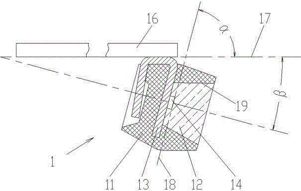
[0035] Embodiment 1 is a light bar that uses bent-leg circuit connectors to tilt down. Figure 7 It is the structural representation of embodiment 1. See Figure 7 A plurality of light-emitting elements 1 are vertically inserted and welded on the light bar PCB 2, and a bent circuit connector 3 is installed, the pin 6 of which is inserted into the light bar PCB 2 for welding connection. The light bar PCB 2 is also equipped with a drive control circuit. One end of the circuit connector 3 is connected to the light bar PCB 2 , and the other end is connected to the column PCB 10 . All the pins at one end of the circuit connector 3 are properly bent at an angle so that there is an angle α between the extension surface of the light bar PCB plane 4 and the extension surface of the column PCB plane 5, and α can be greater than 0° and less than 90° Choose from a range. In this way, when the column PCB 10 is vertically installed on the ground, the light emitting element 1 on the ligh...

Embodiment 2

[0044] Embodiment 2 is another light bar that uses a bent-pin circuit connector to tilt down. Figure 12 It is the structural representation of embodiment 2. See Figure 12 A plurality of light-emitting elements 1 are vertically inserted and welded on the light bar PCB 2 , and the welded light-emitting elements 1 are bent at 90° at the edge of the light bar PCB 2 at the same time using a tooling mold. The light bar PCB 2 is also equipped with a bent-pin circuit connector 3, and the two rows of pins 6 of the circuit connector 3 are pins, which straddle the front and back sides of the light bar PCB 2 for soldering connection, so that the light bar can be made Narrower, improve the air permeability of the light bar screen. The light bar PCB 2 is also equipped with a drive control circuit. One end of the circuit connector 3 is connected to the light bar PCB 2 , and the other end is connected to the column PCB 10 . All the pins at one end of the circuit connector 3 are properly...

Embodiment 3

[0052] Embodiment 3 is a light bar display screen that uses a bent-pin circuit connector to tilt down. Figure 14 It is the structural representation of embodiment 3. See Figure 14 , The light bar display is assembled by one or more light bars that use bent-pin circuit connectors to tilt down. A power supply 12 and a column PCB 10 are installed in the column 11 , and a circuit is installed on the column PCB 10 .

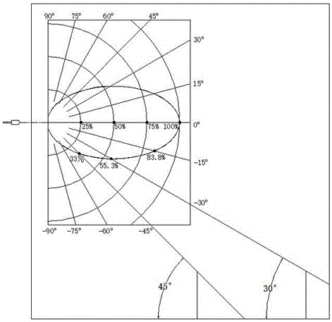
[0053] Apparently, the downward tilting light bar using the bent-leg circuit connector implemented in the present invention realizes the downward tilting of the maximum light intensity angle of the LED element, which improves the perceived brightness of the display screen composed of it and is installed at a high place, thereby improving the brightness of the display screen. energy-saving effect. For example, see figure 1 , assuming that the light distribution curves of LED lamps in Embodiments 1, 2 and 3 are similar figure 1 , and set the maximum light intensi...


PUM


Abstract

The invention provides a downwards inclined light bar provided with bent-pin circuit connectors and a display screen. The light bar comprises a light bar PCB (printed circuit board) provided with multiple light-emitting elements and the circuit connectors; at least one circuit connector capable of being connected with a stand column PCB is mounted on the light bar PCB; one end of each circuit connector is connected with the light bar PCB, the other end is connected with the stand column PCB, and all pins at one end of the circuit connector are bent, so that an included angle alpha is formed between the plane of the light bar PCB or the extension surface of the plane of the light bar PCB and the plane of the stand column PCB or the extension surface of the plane of the stand column PCB and is larger than 0 and smaller than 90 degrees. The maximum light intensity angle of an LED light of the light bar is downwards inclined, the viewing brightness of the display screen mounted in the high position is increased, so that the energy-saving effect of the display screen is improved, the light bar can be narrowed easily, and the void rate is increased. Besides, the improvement cost is low, the risk is low, the structure is simple, and manufacturing and maintenance are easy.

Description

technical field [0001] The invention relates to a light bar with a bent-leg circuit connector, in particular to a structure of a light bar with a bent-leg circuit connector and a display screen formed therefrom. Background technique [0002] figure 1 It is a typical light distribution curve (i.e. light intensity distribution curve) of LED lamps, see figure 1 , it can be known that the relative light intensity in the 0° direction of the light distribution curve (that is, the normal direction of the light-emitting end face) is the largest, which is 100%. In the currently used light bar display, the direction of the maximum light intensity of the chip in the LED component is perpendicular to the wall on which the display is installed (that is, in a horizontal direction). Since the display screens are mostly installed in high places, if the figure 1 For example, when people look up, the relative light intensity is 55.3% when looking up at 30°, and 33% when looking up at 45°. ...

Claims


Application Information

Patent Timeline
IPC IPC(8): G09F9/33
CPCG09F9/33
Inventor 潘尚法
Owner 潘尚法
Why Eureka
Eureka Blog
Learn More