
A thermoelectric power generation device using the waste heat on the surface of the ladle

A technology of thermoelectric power generation and ladle, applied in the directions of generators/motors, electrical components, etc., can solve the problem of inability to use waste heat, and achieve the effect of solving the problem of unavailability of waste heat, simple structure and small volume

Active Publication Date: 2018-11-27
NORTHEASTERN UNIV LIAONING
View PDF5 Cites 0 Cited by
  • Summary
  • Abstract
  • Description
  • Claims
  • Application Information

AI Technical Summary

Problems solved by technology

Due to the limitations of space and technology, it is still impossible to utilize this part of the waste heat with traditional technology

Method used


Image

  • A thermoelectric power generation device using the waste heat on the surface of the ladle
  • A thermoelectric power generation device using the waste heat on the surface of the ladle
  • A thermoelectric power generation device using the waste heat on the surface of the ladle

Examples


Embodiment Construction

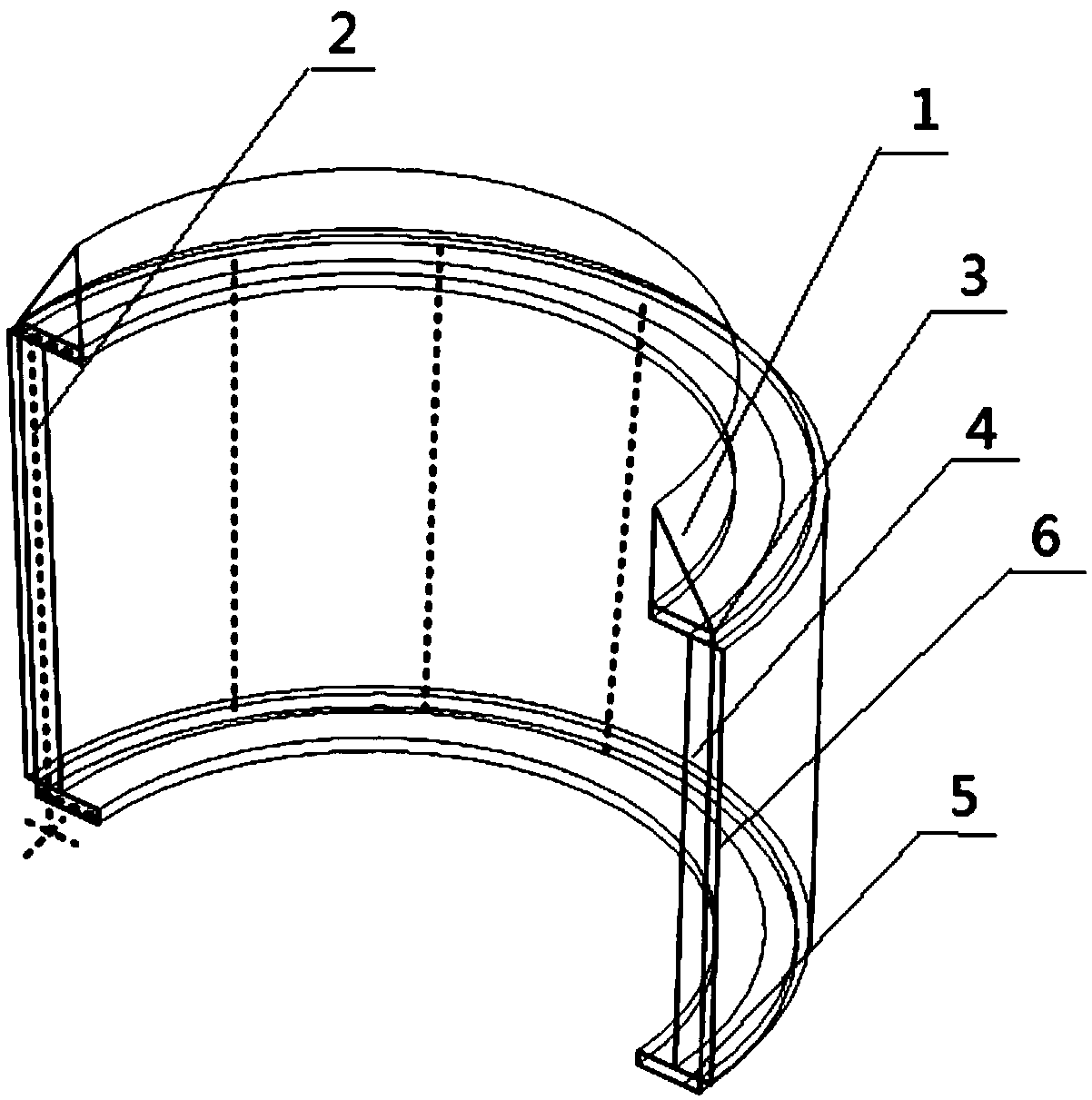
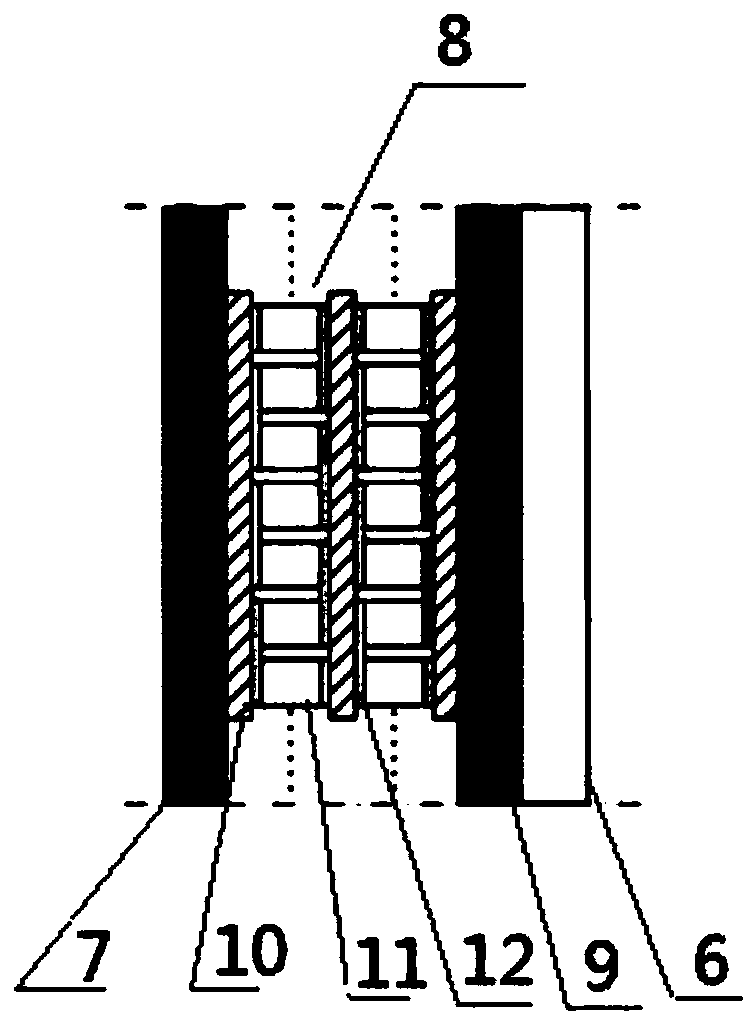
[0031] Such as Figure 1-Figure 4 Shown is a thermoelectric power generation device using waste heat on the surface of a ladle, which is characterized in that the device includes a protective cover 1, a skeleton 2, an upper heat insulation board 3, a thermoelectric system 4, a lower heat insulation board 5 and a cooling system 6;

[0032] The skeleton 2 is a semi-cylindrical bracket;

[0033] The protective cover 1 is welded on the frame 2;

[0034] The upper insulation board 3, the thermoelectric system 4 and the lower insulation board 5 are all fixed on the framework 2 by bolts, forming a semi-cylindrical shape;

[0035] The cooling system 6 is placed outside the thermoelectric system 4;

[0036] The device is composed of two semi-cylindrical shapes.

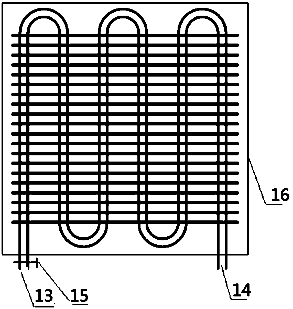
[0037] The cooling system 6 includes a flow control valve 15, a water cooling radiator 16, a cooling water inlet 13 and a cooling water outlet 14;

[0038] The water-cooled radiator 16 is closely attached to the heat-dissi...


PUM


Abstract

The invention discloses a thermoelectric generation device using steel ladle surface waste heat. The device comprises a protective cover, a skeleton, an upper heat insulating plate, a thermoelectric system, a lower heat insulating plate and a cooling system. The skeleton is a semi-cylindrical support; the protective cover is welded on the skeleton; the upper heat insulating plate, the thermoelectric system and the lower heat insulating plate are fixed on the skeleton by bolts to form a semi-cylindrical shape; the cooling system is arranged outside the thermoelectric system; and the device is composed of two semicircular cylinders. The technical scheme of the invention has the characteristics of simple structure, small size, no mechanical movement and no noise, so that the waste heat recovery and utilization in the limited space can be realized.

Description

technical field [0001] The invention relates to the field of iron and steel metallurgy, in particular to a thermoelectric power generation device utilizing the waste heat on the surface of a ladle. Background technique [0002] In the steelmaking process of iron and steel production, the refining, transportation, standing, pouring and other links of high-temperature molten steel (about 1600 ° C) are all carried out in the ladle container. Although the development of heat preservation technology has reduced heat loss to a certain extent, due to the Due to the huge temperature difference between the liquid and the external environment, there is still considerable heat on the surface of the ladle that is inevitably lost to the environment. According to the field test, when the molten steel is contained, the surface temperature of the ladle is in the temperature range of 100-400°C. Due to the limitations of space and technology, it is still impossible to utilize this part of wa...

Claims


Application Information

Patent Timeline
Patent Type & Authority Patents(China)
IPC IPC(8): H02N11/00
CPCH02N11/002
Inventor 孟祥宁朱苗勇卢百意田月
Owner NORTHEASTERN UNIV LIAONING
Learn More