
Measurement jig

A jig and voltage pin technology, applied in error detection/correction, instruments, electrical digital data processing, etc., can solve the problem of insufficient test jig, and achieve the effect of diversified measurement functions

Active Publication Date: 2017-06-27
GIGA BYTE TECH CO LTD
View PDF5 Cites 0 Cited by
  • Summary
  • Abstract
  • Description
  • Claims
  • Application Information

AI Technical Summary

Problems solved by technology

[0004] The present invention is to provide a measurement fixture to overcome the problem that common test fixtures are not enough due to the various setting configurations of the current mainboard

Method used


Image

  • Measurement jig
  • Measurement jig
  • Measurement jig

Examples


Embodiment Construction

[0029] The detailed features and advantages of the present invention are described in detail below in the embodiments, which are sufficient to enable those skilled in the art to understand the technical content of the present invention and implement it accordingly. The related objects and advantages of the present invention can be easily understood by those skilled in the art. The following examples are to further describe the viewpoints of the present invention in detail, but not to limit the scope of the present invention in any way.

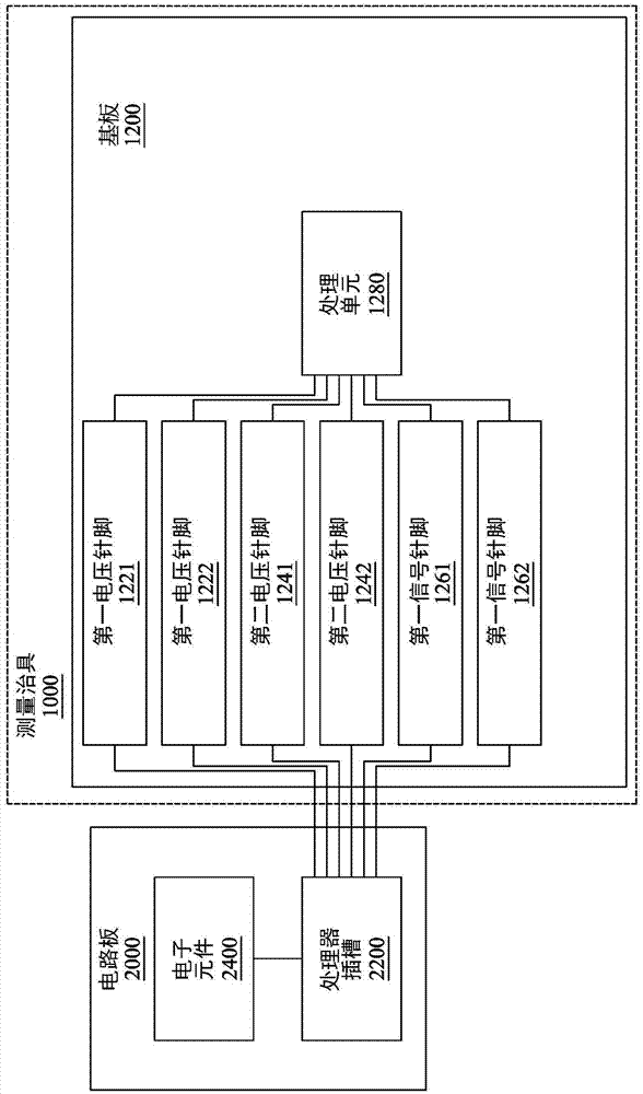
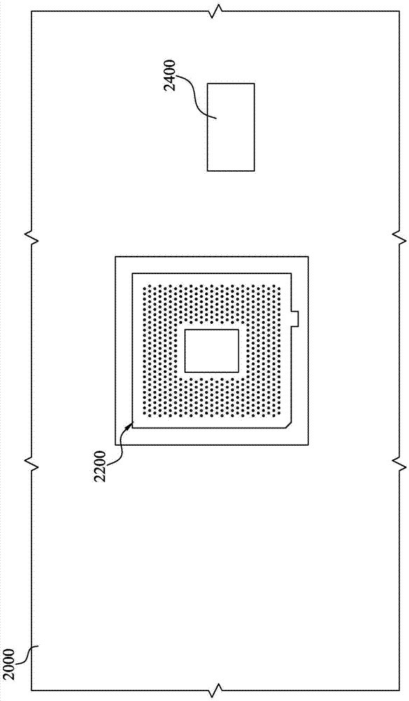
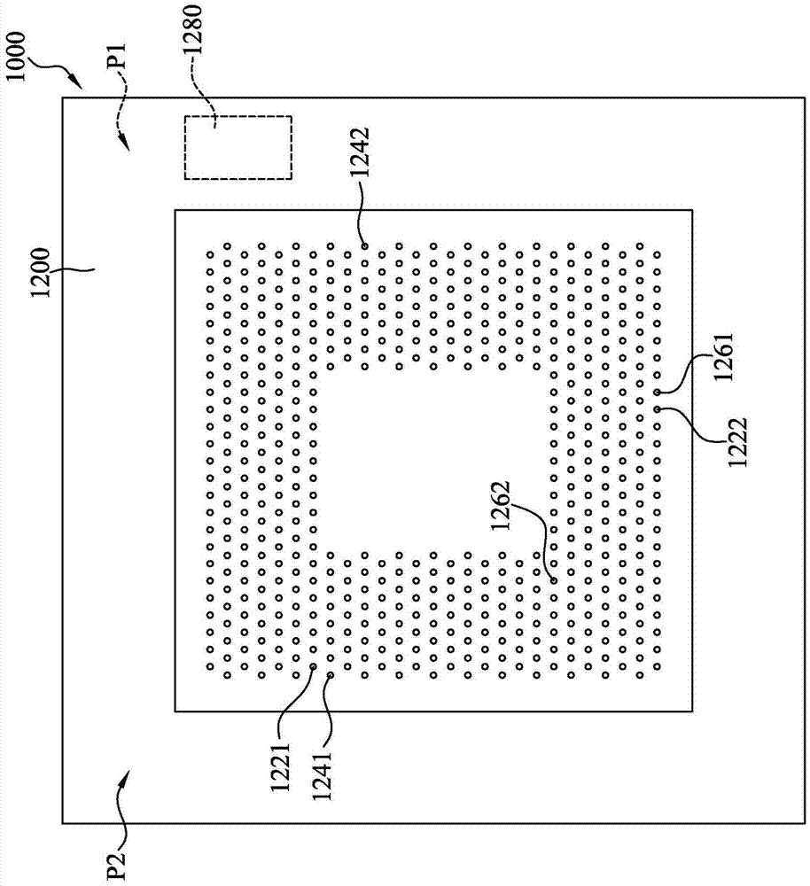
[0030] Please refer to figure 1 , figure 1 It is a functional block diagram of a measurement fixture according to an embodiment of the present invention. Such as figure 1 As shown, the measurement fixture 1000 is suitable for being inserted into the processor socket 2200 on the motherboard 2000 . The measurement fixture 1000 includes a substrate 1200 , first voltage pins 1221 , 1222 , second voltage pins 1241 , 1242 , first signal pins 126...


PUM


Abstract

The invention discloses a measurement jig, which is suitable for a processor slot inserted in a mainboard. The measurement jig comprises a substrate, at least one first voltage pin, at least one second voltage pin, at least one first signal pin and a processing unit. The substrate has a first surface and a second surface. The at least one first voltage pin, the at least one second voltage pin and the at least one first signal pin are located on the second surface. The processing unit is located on the first surface. The processing unit is electrically connected to the at least one first voltage pin, the at least one second voltage pin and the at least one first signal pin. When the measurement jig is inserted in the processor slot, the processing unit reads at least one first voltage value from the at least one first voltage pin, reads at least one second voltage value from the at least one second voltage pin, and reads at least one third voltage value from the at least one first signal pin. The measurement jig provided by the invention can measure the mainboard with different set configurations.

Description

technical field [0001] The invention relates to a measuring fixture, in particular to a measuring fixture for electronic components. Background technique [0002] As a communication medium for various electronic components in electronic products, the motherboard is equipped with the above-mentioned various electronic components to provide users with various functions. In order to meet different requirements, corresponding electronic products require different levels or different types of computing performance. Even for the same type of electronic products, manufacturers will launch different series of product series due to different customer groups. [0003] In the past, because there were not many types of electronic products, the main board was set to correspond to electronic components of a certain specification. For example, for a motherboard of a computer, its components may all be set in a certain configuration to cooperate with a central processing unit of a certain...

Claims


Application Information

Patent Timeline
Patent Type & Authority Applications(China)
IPC IPC(8): G06F11/267
CPCG06F11/267
Inventor 李延霖黄劲勋
Owner GIGA BYTE TECH CO LTD
Learn More