
Multifunctional transmitter

A transmitter and multi-functional technology, applied in the field of geophysical exploration, can solve the problems of large volume and weight of the generator, inconvenient transportation of the generator, and increase the difficulty of survey work, etc., to achieve volume and weight reduction and strong equipment scalability , low cost effect

Active Publication Date: 2013-05-15
北京南风科工应用技术有限公司 +1
View PDF0 Cites 0 Cited by
  • Summary
  • Abstract
  • Description
  • Claims
  • Application Information

AI Technical Summary

Problems solved by technology

The greater the power, the greater the volume and weight of the generator, and the existing portable alternators cannot be connected in series and parallel
Geophysical exploration is mostly field work, the working environment is complicated, and the heavy generator is very inconvenient to transport, and according to different measurement requirements, it is often necessary to carry transmitters and generators of various power specifications, which increases the difficulty of the survey work
[0006] In addition, with the gradual expansion of the application scope of the controllable source audio magnetotelluric sounding method, the measurement requirements are also more diverse. From the perspective of function and cost, the traditional transmitter power specification is fixed, and the functions that users can realize are single. Practical flexibility is poor, and multiple transmitters must be purchased to meet different needs, and the cost is high

Method used


Image

  • Multifunctional transmitter
  • Multifunctional transmitter
  • Multifunctional transmitter

Examples


Embodiment 1

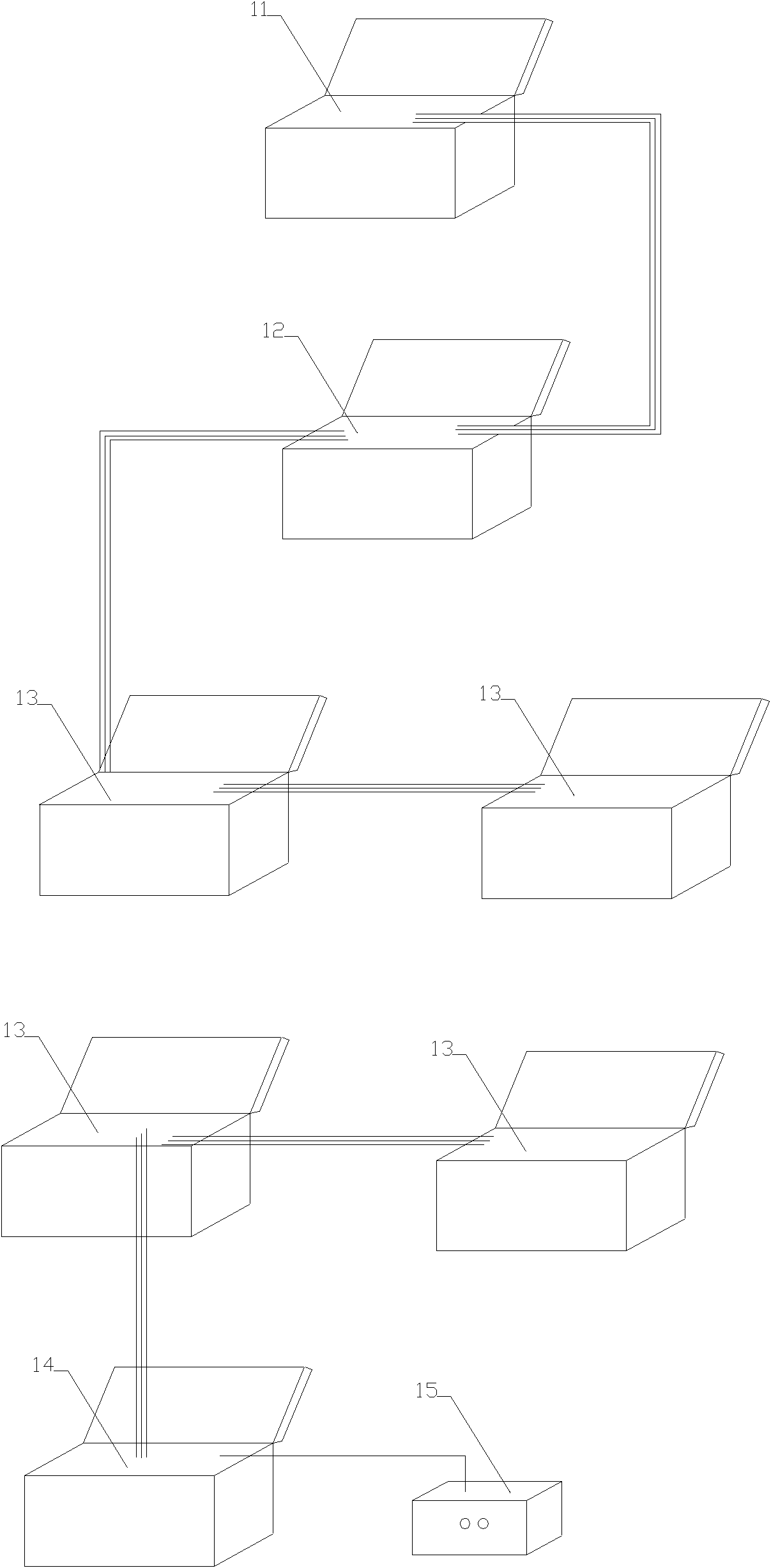
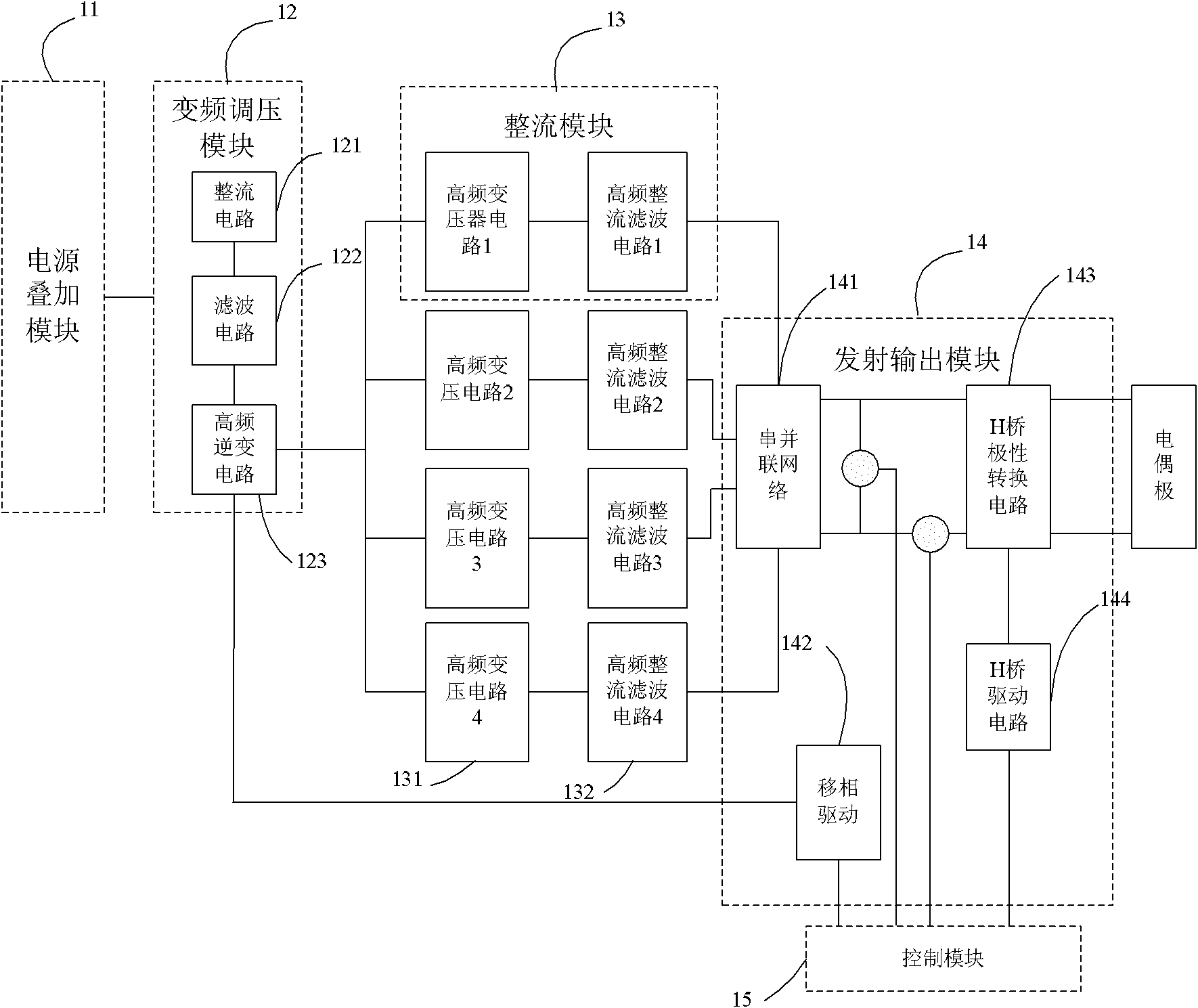
[0047] figure 1 It is a schematic structural diagram of a multifunctional transmitter in this embodiment, and the multifunctional transmitter includes a plurality of functional modules that are physically separated from each other. As shown in the figure, the plurality of functional modules include: a power superposition module 11, a frequency conversion Compression module 12, at least two rectification modules 13, emission output module 14, control module 15; wherein,

[0048] The power superposition module 11 is connected to a plurality of external power sources (not shown in the figure), and is used to make the alternating currents of the plurality of external power sources in phase and superimpose the input power of the power sources to obtain alternating current with a first voltage and a first frequency;

[0049] The frequency conversion and voltage regulation module 12 is used to adjust the first voltage and the first frequency to obtain alternating current with the sec...

Embodiment 2

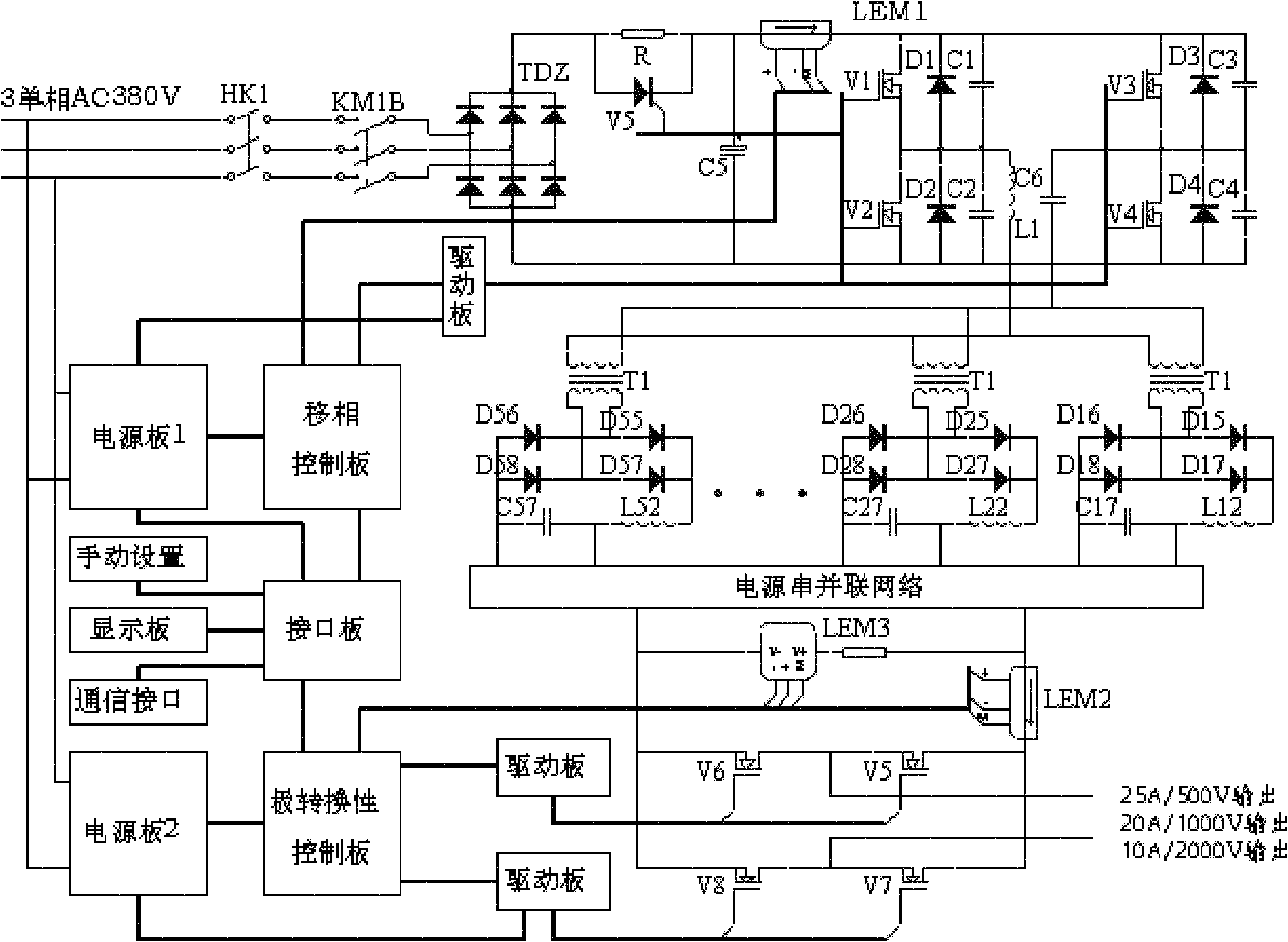
[0088] Figure 5 It is a block diagram of the electrical structure of the multifunctional transmitter of this embodiment. The difference from the first embodiment is that the multifunctional transmitter also includes a protection module 16. As shown in the figure, the protection module 16 is connected to the control module 15. It is used to protect each functional module from overcurrent, overheating or load short circuit. When a fault occurs, it will quickly turn off the IGBT and cut off the input main power supply. The protection module 16 includes an overcurrent protection circuit, an overheat protection circuit and a load short circuit protection circuit. Among them, the overcurrent protection circuit detects the bus current through the current LEM and compares it with the set bus current threshold, and protects when the bus current is greater than the threshold. The overheating protection circuit detects the temperature at the radiator IGBT through the temperature relay,...


PUM


Abstract

The invention provides a multifunctional transmitter, which comprises a plurality of functional modules physically separated from each other. The functional modules comprise a power supply superposition module, a frequency conversion and voltage regulation module, at least two rectification modules, a transmitting and outputting module and a control module, wherein the power supply superposition module is connected with a plurality of external power supplies, and is used for arranging alternating currents of the plurality of external power supplies at the same phase and superposing input powers of the power supplies so as to obtain an alternating current with a first voltage and a first frequency, the frequency conversion and voltage regulation module is used for regulating the first voltage and the first frequency so as to obtain an alternating current with a second voltage and a second frequency, the at least two rectification modules are used for converting the frequency-converted and voltage-regulated alternating current into a direct current, an output end of the transmitting and outputting module is connected with a transmitting antenna for the series or parallel connection of the at least two rectification modules, and the transmitting and outputting module is used for adjusting the output waveform and frequency, and the control module is used for controlling the waveform, clock and frequency of a transmitting signal. The multifunctional transmitter provided by the invention has the advantages of many measurement functions, convenience for transportation, high expandability and low cost.

Description

technical field [0001] The invention relates to the technical field of geophysical exploration, in particular to a multifunctional transmitter. Background technique [0002] Electrical prospecting is one of the main branches of geophysical prospecting technology. Electrical prospecting is to explore geological structures by utilizing the differences in electrical properties between various rocks and strata in the earth's crust. In electrical prospecting, there are currently four main types of electrical properties or physical parameters of rocks and formations, namely resistivity, magnetic permeability, polarization characteristics and dielectric constant. [0003] As a kind of electrical survey, the controlled source audio frequency magnetotelluric sounding method (CSAMT) has attracted the attention of the industry due to its unique advantages such as high signal strength, strong anti-interference ability, and high resolution. This method uses a controllable artificial fie...

Claims


Application Information

Patent Timeline
Patent Type & Authority Patents(China)
IPC IPC(8): G01V3/12
Inventor 方励汪东平张小华张辉
Owner 北京南风科工应用技术有限公司
Learn More