A receiver without off-chip filter

A filter and receiver technology, applied in the field of RF front-end, can solve the problems of reducing signal-to-noise ratio, increasing power consumption, noise signal, etc., achieving low noise figure, improving linearity, and eliminating compromise relations

Active Publication Date: 2019-05-24
RDA MICROELECTRONICS SHANGHAICO LTD
View PDF5 Cites 0 Cited by
  • Summary
  • Abstract
  • Description
  • Claims
  • Application Information

AI Technical Summary

Problems solved by technology

The disadvantage of this scheme is that the introduced buffer will add additional power consumption, and it will also introduce noise and attenuate the signal
At the same time, due to the nonlinearity of the buffer itself, it will also reduce the signal-to-noise ratio of the signal

Method used


Image

  • A receiver without off-chip filter
  • A receiver without off-chip filter
  • A receiver without off-chip filter

Examples


Embodiment Construction

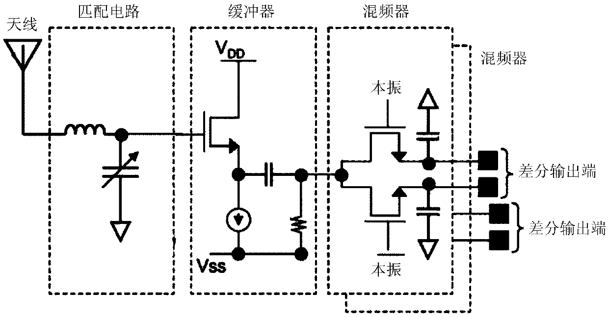
[0028] see Figure 4 , which is the first embodiment of the receiver provided by the present application that omits the off-chip filter. The receiver shown in the first embodiment includes a matching network, a passive filter, a baseband amplifier and a filter in sequence from the antenna down. The matching network includes a capacitor C1 and an inductor L1 connected in series. The first end of the capacitor C1 is used as the input end of the matching network to receive the radio frequency signal from the antenna. The second end of the capacitor C1 is connected to the first end of the inductor L1 as the output end of the matching network. The second end of the inductor one L1 is grounded. The passive filter has N channels connected in parallel, and each channel consists of a switching tube T N and a sampling capacitor C LN connected in series, and the switching tube T in each channel N are driven by a carrier signal LO N Control it on or off. see Figure 5 , the N swi...


PUM


Abstract

The application discloses a receiver that omits off-chip filter. The receiver is connected with a matching network, a passive filter, a baseband amplifier and a filter in sequence from an antenna downward. The matching network is composed of one or more capacitors or inductors. The passive filter has multiple channels connected in parallel. Each channel is composed of a switch tube and a sampling capacitor connected in series and the switching on or off of the switch tube in each channel is controlled by a carrier signal. The high level pulses of the carrier signals are not overlapped. During the high level pulse period of some carrier signal, the switch tube is switched on under the control of the carrier signal, and the other switch tubes are all switched off. The baseband amplifier and the filter further amplify and filter the intermediate frequency or the baseband signal after down conversion. The receiver omits the off-chip surface acoustic wave filter, realizes the lower noise coefficient, improves the capability of eliminating the out-of-band obstruction, improves the linearity, and eliminates the tradeoff relation between the input matching and the baseband amplifier.

Description

technical field [0001] The present application relates to a radio frequency receiver, in particular to a radio frequency front end thereof. Background technique [0002] A transceiver (transceiver) includes a transmitter (transmitter) and a receiver (receiver). The RF front end of the receiver usually refers to the circuit from the antenna to the mixer, including the mixer. In CMOS RF transceivers used in mobile communications such as 2G, 3G, and 4G, the high-power signal generated by the transmitter will be coupled to the receiver in various ways, which will cause the receiver to face the risk of saturation. At the same time, the signal received by the antenna is often accompanied by a high-power blocking signal, which will also saturate the receiver. In order to improve the receiver's suppression effect on out-of-band blocking, some existing receiver radio frequency front-end solutions have been proposed. [0003] In April 2011, "IEEE Journal of Solid-State Circuits" (I...

Claims


Application Information

Patent Timeline
Patent Type & Authority Patents(China)
IPC IPC(8): H04B1/18H04B1/10
CPCH04B1/10H04B1/18
Inventor 刘政清林甲富柯庆福
Owner RDA MICROELECTRONICS SHANGHAICO LTD
Why Eureka
Try Eureka