
Rapid extraction method based on self-luminous ball camera calibration target

A camera calibration and extraction method technology, which is applied in the field of rapid extraction, can solve the problems of uneven distribution of ceramic ball target images, difficulty in ensuring the same clarity of calibration images, and uneven distribution of calibration target images. The effect of uneven intensity distribution, easy disassembly, and uniform brightness

Active Publication Date: 2017-06-23
DALIAN UNIV OF TECH
View PDF1 Cites 14 Cited by
  • Summary
  • Abstract
  • Description
  • Claims
  • Application Information

AI Technical Summary

Problems solved by technology

[0004] In order to solve the problem of uneven gray scale distribution of the ceramic ball target image in the existing three-dimensional calibration device in the process of camera calibration, the present invention invented a rapid extraction method based on self-illuminating spherical camera calibration target
Its purpose is to solve the problems such as the difficulty of automatic recognition of spatial points in the camera calibration process, and when the viewing angles of the two cameras are relatively large, it is difficult to ensure that the calibration images of all the feature points of the two cameras have the same clarity. It can be realized by arranging in the measurement space Self-illuminating spherical calibration target for quick camera identification and high-precision calibration
It overcomes the difficulty of automatic recognition of spatial points in the camera calibration process of the existing 3D calibration device. When the viewing angles of the two cameras are relatively large, it is difficult to ensure that the calibration images of all the feature points of the two cameras have the same clarity and the calibration target captured With defects such as uneven distribution of image grayscale, it has a wide range of application prospects

Method used


Image

  • Rapid extraction method based on self-luminous ball camera calibration target
  • Rapid extraction method based on self-luminous ball camera calibration target
  • Rapid extraction method based on self-luminous ball camera calibration target

Examples


Embodiment Construction

[0028] The specific embodiments of the present invention will be described in detail below in conjunction with technical methods and accompanying drawings.

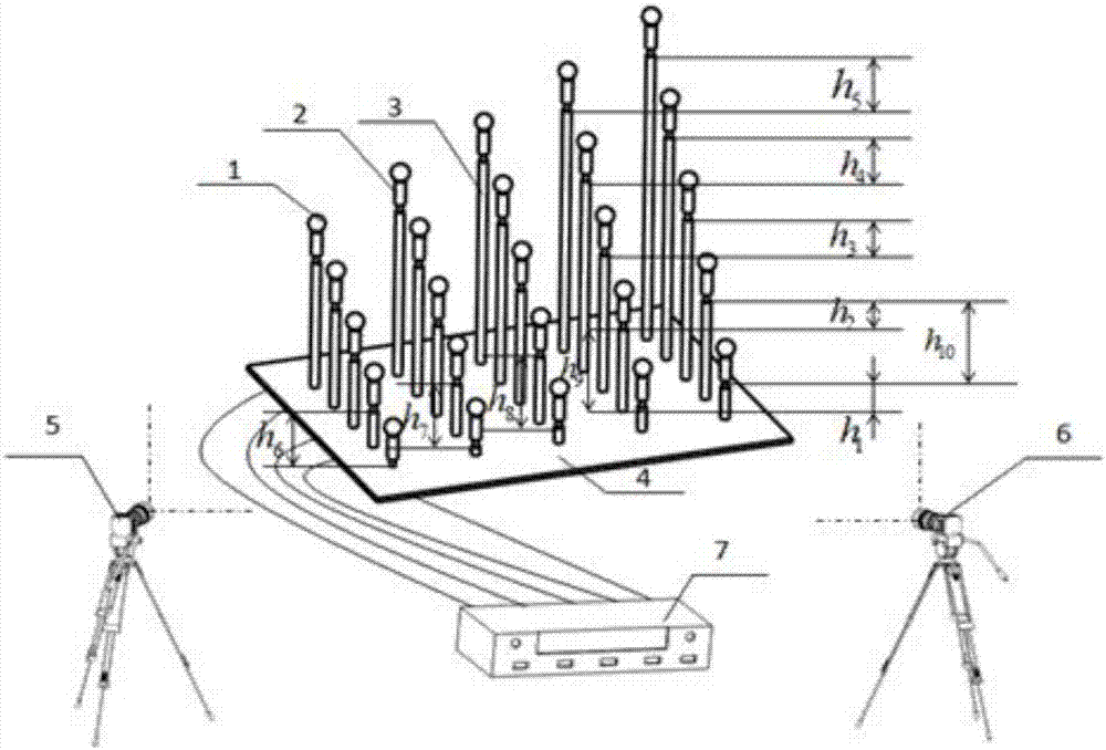
[0029] Before calibration, install the spatial three-dimensional calibration target first, and then use a three-dimensional coordinate measuring machine to measure to determine the precise three-dimensional position information of the center of the self-luminous ball target 1, and use the left and right cameras 5 and 6 of the binocular vision system to pair the self-luminous ball Shoot the target 1, extract the characteristic information of the center of the self-luminous ball target 1 in the picture, and obtain the two-bit pixel coordinates of the center. Finally, based on the direct linear transformation method, the internal and external parameters of the left and right cameras 5 and 6 of the binocular vision system are obtained to realize the stereo calibration of the cameras in three-dimensional space. Specific steps ...


PUM


Abstract

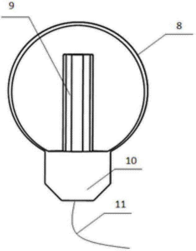
The invention relates to a rapid extraction method based on a self-luminous ball camera calibration target, and belongs to the field of visual measurement. Before calibration, the three-dimensional calibration target is mounted, a three-coordinate measuring machine is used for measurement, accurate 3D position information of the center of the self-luminous ball target is determined, left and right cameras in a binocular visual system are used to shoot the self-luminous ball target, characteristic information of the center of the self-luminous ball target is extracted from pictures, and a 2D pixel coordinate of the center of the self-luminous ball target is calculated. On the basis of a direct linear transformation method, internal and external parameters of the left and right cameras are calculated, and stereoscopic calibration of the cameras in the 3D space is realized. The self-luminous ball targets including different numbers of rows are different in brightness, different grayscale thresholds are set, and thus, space information is identified rapidly and automatically, and the left and right cameras are calibrated rapidly in high precision in the calibration process.

Description

technical field [0001] The invention belongs to the field of visual measurement, and relates to a rapid extraction method of a self-illuminating spherical camera based on a three-dimensional calibration target. The method realizes the rapid identification and extraction of the camera during the calibration process. Background technique [0002] In recent years, measurement systems based on machine vision have been increasingly used in the processing, assembly and quality inspection of the aviation industry. Camera calibration is a necessary step before visual measurement. Its goal is to establish the mapping relationship between three-dimensional space points and their matching image points. The calibration accuracy of the camera determines the final size measurement accuracy. Therefore, it is particularly important to choose a convenient, fast, and high-precision calibration target. . In the process of camera calibration, in order to reduce the number of shots and increase...

Claims


Application Information

Patent Timeline
IPC IPC(8): G06T7/80G01B11/00
CPCG01B11/00
Inventor 刘巍赵海洋兰志广张致远叶帆张洋杨帆贾振元
Owner DALIAN UNIV OF TECH
Learn More