
Cyclonic collecting device for lampblack of range hood

A range hood and oil fume technology, applied in the direction of oil fume removal, application, household stoves, etc., can solve the problems of oil fume inaccessibility, extraction, loud noise, etc., and achieve the effect of reducing working noise, reducing power demand, and expanding the range of suction

Inactive Publication Date: 2017-06-23
WATERLOO CFD ENG CONSULTING INC
View PDF8 Cites 1 Cited by
  • Summary
  • Abstract
  • Description
  • Claims
  • Application Information

AI Technical Summary

Problems solved by technology

[0002] The range hood generally generates a certain negative pressure at the smoke outlet through the rotating impeller, and then attracts the nearby airflow to flow in. However, in fact, this attraction decreases rapidly as it moves away from the smoke outlet. Under the standard installation height of the range hood, The suction force of the range hood has reached the surface of the cooktop very weakly, so the oil fume cannot get enough power to move to the smoke outlet
Furthermore, the direction of the suction force generated by the range hood is divergent, and the range hood draws a lot of air from other directions, not just the oil fume from below, resulting in a small amount of oil fume per unit time. But if the cooking fume cannot be sucked away in time, it will be affected by gravity and spread to all directions, and cannot be sucked away by the range hood
Therefore, the range hood in the related art has a limited suction range, and the suction range cannot be increased, and the range hood cannot be effectively improved, and the energy consumption is large and the noise is large.

Method used


Image

  • Cyclonic collecting device for lampblack of range hood
  • Cyclonic collecting device for lampblack of range hood
  • Cyclonic collecting device for lampblack of range hood

Examples


Embodiment 1

[0101] The projection of the hood body S1 of the range hood S on the horizontal plane is roughly rectangular, and the gas pipe 100 of the oil fume swirling device S2 of the range hood includes two, and the two gas pipes 100 are arranged at the rear of the lower end of the hood body S1 and Spaced apart in the left-right direction.

[0102] Specifically, such as Figure 6 and Figure 7 As shown, in this embodiment, the range hood S is mainly composed of the range hood S1 and the range hood S2. The outer contour of the lower end of the range hood S1 roughly forms a rectangle arranged in a horizontal plane. The range hood S1 The lower end face is provided with at least one fume suction port.

[0103] The oil fume swirling device S2 includes two air pipes 100, and the two air pipes 100 are arranged at a distance from the side of the hood body S1 away from the user (such as Figure 6 shown rear side), each trachea 100 along the vertical direction (as Figure 6 (shown in the up a...

Embodiment 2

[0110] The projection of the hood body S1 of the range hood S on the horizontal plane is roughly rectangular, and the gas pipe 100 of the oil fume swirling device S2 of the range hood includes three, and the three gas pipes 100 are respectively arranged at the rear of the lower end of the hood body S1 And arranged at intervals from each other along the left and right directions. The trachea 100 in the middle can discharge air to the trachea 100 on the left and / or the trachea 100 on the right, thereby adding a tangential shearing force to the smoke source of the stove eye at the corresponding position, so that the formed tornado effect can be obtained. Strengthen, and then improve the fume effect of the range hood S.

[0111] Optionally, among the three air pipes 100, the left air pipe 100 is located on the left side of the leftmost stove eye on the stove T, the right air pipe 100 is located on the right side of the rightmost stove eye on the stove T, and the middle air pipe 10...

Embodiment 3

[0119] The outer contour of the lower end of the hood body S1 of the range hood S is roughly formed in a rectangle, and the gas pipes 100 of the oil fume swirling device S2 of the range hood include four, and the four air pipes 100 are respectively arranged on the four lower ends of the hood body S1. At right angles.

[0120] Specifically, such as Figure 10 and Figure 11 As shown, in this embodiment, the range hood S is mainly composed of the range hood S1 and the range hood S2. The outer contour of the lower end of the range hood S1 roughly forms a rectangle arranged in a horizontal plane. The range hood S1 The lower end face is provided with at least one fume suction port.

[0121] The oil fume swirling device S2 includes four air pipes 100, and the four air pipes 100 are arranged at intervals along the circumference of the lower end surface of the oil fume body, and each air pipe 100 is vertically (such as Figure 10 (shown in the up and down direction), the upper end ...


PUM


Abstract

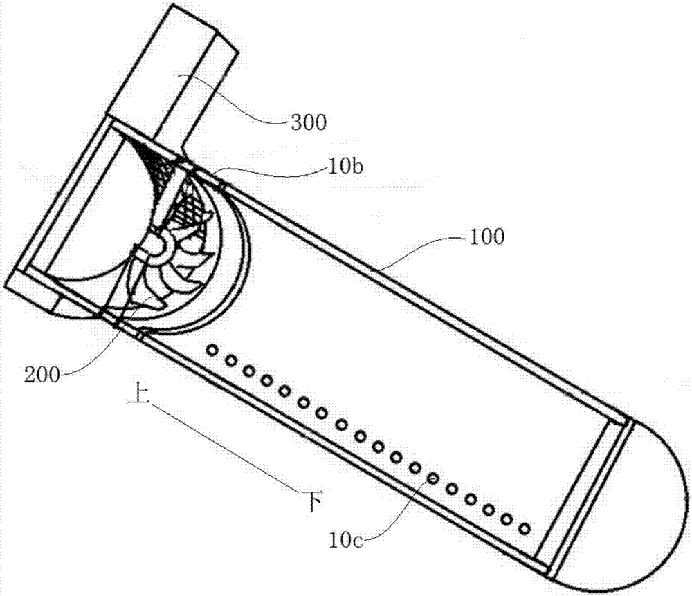
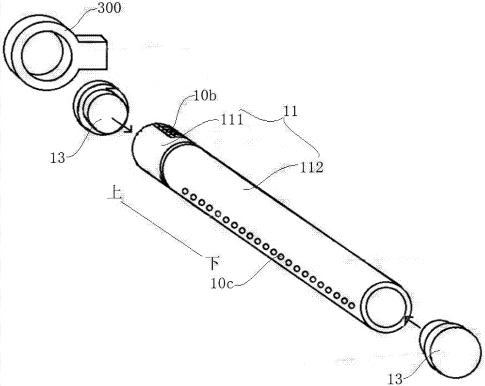
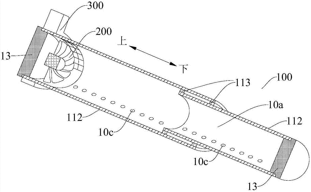
The invention discloses a cyclonic collecting device for lampblack of a range hood. The cyclonic collecting device comprises at least one air pipe; the air pipe is internally provided with an air flue in which an air inlet and an air outlet are formed; and the air pipe forms a tornado-shaped cyclone for cyclonically collecting lampblack by virtue of an air flow sprayed from the air outlet. According to the cyclonic collecting device for lampblack of the range hood in the embodiment of the invention, the air inlet and the air outlet communicating with the air flue are formed in the air pipe, the air flow is discharged from the air outlet of the air pipe to generate a strong shearing force for the ambient air and the lampblack to drive the ambient air and the lampblack to flow to finally form the tornado-shaped cyclone, the lampblack is guaranteed to spirally ascend under the action of the strong suction force of the cyclone and is prevented from being diffused around, and the suction force range of the range hood is widened, so that the power demand of the range hood is reduced, the energy consumption is reduced, furthermore, the working noise of the range hood is reduced, and the quality of the range hood is improved.

Description

technical field [0001] The invention relates to the technical field of kitchen appliances, in particular to a fume swirling device for range hoods. Background technique [0002] The range hood generally generates a certain negative pressure at the smoke outlet through the rotating impeller, and then attracts the nearby airflow to flow in. However, in fact, this attraction decreases rapidly as it moves away from the smoke outlet. Under the standard installation height of the range hood, The suction force of the range hood has reached the surface of the stove very weakly, so the oil fume cannot get enough power to move to the smoke outlet. Furthermore, the direction of the suction force generated by the range hood is divergent, and the range hood draws a lot of air from other directions, not just the oil fume from below, resulting in a small amount of oil fume per unit time. But if the cooking fume cannot be sucked away in time, it will be affected by gravity and spread to al...

Claims


Application Information

Patent Timeline
Patent Type & Authority Applications(China)
IPC IPC(8): F24C15/20
CPCF24C15/20
Inventor 李辰光连复桑嵇华
Owner WATERLOO CFD ENG CONSULTING INC
Learn More