
Long-distance injection pipe down pipe device

A grouting pipe, long-distance technology, used in wellbore/well components, earthwork drilling, sealing/packing, etc., can solve the problem of large positioning error of grouting pipe, damaged grouting pipe structure, and work efficiency Influence and other issues, to achieve the effect of flexible production and use, improved quality and efficiency, and strong output power

Inactive Publication Date: 2017-06-23
HENAN POLYTECHNIC UNIV
View PDF6 Cites 0 Cited by
  • Summary
  • Abstract
  • Description
  • Claims
  • Application Information

AI Technical Summary

Problems solved by technology

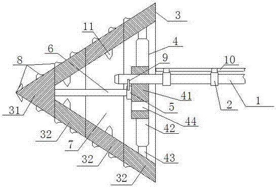
[0002] At present, in the process of exploration and mining of coal and other mineral resources, it is often necessary to perform operations such as grouting and sealing of drilling holes in the formation. In actual construction, it is found that on the one hand, the strength of the grouting pipe itself is relatively small; It cannot be carried out due to the obstruction of objects, or the structure of the grouting pipe is damaged and the positioning error of the grouting pipe is relatively large, which seriously affects the work efficiency and quality of the grouting operation for the borehole. In view of this problem, Since there is no effective countermeasure equipment at present, the borehole can only be cleaned by high-pressure air or high-pressure water, and then the grouting pipe can be positioned. Although it can meet the needs of use to a certain extent, the operation is complicated and the energy consumption is low. The resource consumption is large, which increases the work cost and labor intensity of the drilling and grouting operation. This problem is particularly prominent when grouting some deep drilling holes, and the cleaning of the drilling holes often occurs. As a result, the work efficiency is seriously affected. Therefore, in view of this problem, it is urgent to develop a special equipment for the downpipe of the grouting pipe to meet the needs of actual use.

Method used


Image

  • Long-distance injection pipe down pipe device

Examples


Embodiment Construction

[0012] In order to make the technical means, creative features, goals and effects achieved by the present invention easy to understand, the present invention will be further described below in conjunction with specific embodiments.

[0013] like figure 1 The long-distance grouting pipe lowering equipment includes a high-pressure driving water pipe 1, a tapered plug, and a connecting buckle 2. The tapered plug includes a breaking head 3, a bearing frame 4, a hydraulic motor 5 and a transmission shaft 6, The barrier head 3 is a hollow cone structure, the barrier breaking head 3 is provided with a bearing cavity 7, the bearing cavity 7 is coaxially distributed with the barrier breaking head 3, and at least two cutting edges 8 are evenly distributed on the outer surface of the barrier breaking head 3, and each cutting edge 8 are distributed in a spiral shape around the axis of the barrier-breaking head 3. The transmission shaft 6, the carrier frame 4 and the hydraulic motor 5 are ...


PUM


Abstract

The invention relates to a long-distanceinjectionpipedown pipe device.The device comprisesa high pressure drive pipe, acone shapeplug, a connection buckle, the cone shapeplugcomprises a broken barrier head, abearing frame, a hydraulic motor and a drive shaft, the broken barrier head is a hollow cone structure, a bearing cavity is arranged inside the broken barrier head, the drive shaft, thebearing frame and the hydraulic motor are all embedded inthe bearing cavity body, the frontend of the drive shaft and the inner surface of the broken barrier head are connected, the tail end is connectedwiththe hydraulic motor, the bearing frame comprises abearing disc and a connection spoke rod, the connection board through a positioning hole isconnected with thehigh pressure drive pipe, the high pressure drive pipe through a guide pipeis mutually connected with the hydraulic motor,and a number of connectionbuckles are evenly distributed on the high pressure drive water pipe along theaxial direction of the high-voltage drive pipe. The device on the one hand can effectively improve the breakthrough ability of the injection pipeto the obstacles in the drill holes when in the process of down drilling, the layout pipe and the work efficiency and the quality of the injection pipe positioning are improved, on the other hand the obstacles in the drill holes are cleaned up and broken,and the drill hole qualityis improved.

Description

technical field [0001] The invention relates to a long-distance grouting pipe lowering equipment, which belongs to the technical field of geological exploration and mining. Background technique [0002] At present, in the process of exploration and mining of coal and other mineral resources, it is often necessary to perform operations such as grouting and sealing of drilling holes in the formation. In actual construction, it is found that on the one hand, the strength of the grouting pipe itself is relatively small; It cannot be carried out due to the obstruction of objects, or the structure of the grouting pipe is damaged and the positioning error of the grouting pipe is relatively large, which seriously affects the work efficiency and quality of the grouting operation for the borehole. In view of this problem, Since there is no effective countermeasure equipment at present, the borehole can only be cleaned by high-pressure air or high-pressure water, and then the grouting...

Claims


Application Information

Patent Timeline
IPC IPC(8): E21B23/08E21B31/00E21B33/13
CPCE21B23/08E21B31/00E21B33/13
Inventor 罗平平陈蕾陈新明
Owner HENAN POLYTECHNIC UNIV
Learn More