Hollow floor of through beam

A cavity floor and main beam technology, applied to floors, building components, buildings, etc., can solve problems such as construction, weight, and cost

Inactive Publication Date: 2017-06-23
王海崴 +1
View PDF7 Cites 1 Cited by
  • Summary
  • Abstract
  • Description
  • Claims
  • Application Information

AI Technical Summary

Problems solved by technology

[0005] The purpose of the present invention is to promote the integrated process of building energy saving, using a cavity floor with through-beams to upgrade the existing cavity floor structure system; making full use of the advantages of factory industrialization, making ribbed steel mesh panels, and producing them near the construction site Foamed cement blocks are assembled into a steel mesh body at the construction site to solve the problems of construction, environmental protection, weight, production, transportation, work efficiency, and cost existing in the existing cavity floor technology; transform the existing cavity floor structure technology Upgrading and replacement; at the same time improve the building quality and lay a solid foundation for the multi-functional application of cavity floor slabs

Method used


Image

  • Hollow floor of through beam
  • Hollow floor of through beam
  • Hollow floor of through beam

Examples


Embodiment Construction

[0020] The invention will be further described below in conjunction with the accompanying drawings.

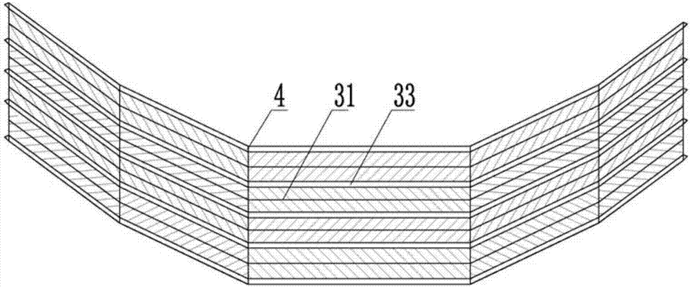
[0021] figure 1 It is an elevation view of a perforated steel mesh body of a hollow floor through beam of the present invention. When the present invention is implemented, the ribbed steel mesh 2 prepared from the factory is transported to the construction site; Produce foamed cement blocks of the required specifications nearby or at the construction site; place foamed cement blocks at 4 places on the cut-to-length mold marks of the ribbed steel mesh, and wrap the foamed cement blocks with the ribbed steel mesh along the scaled die marks, The foam cement block is a support foam cement block 34 and a plugging foam cement block 35, a prefabricated notch 36 is arranged at the lower end of the support foam cement block 34, and N reserved holes 37 are arranged in the support foam cement block; There is a prefabricated notch 3 on the inner wall of the cement block; the two ends of ...


PUM


Abstract

The invention provides a cavity floor slab with a through-beam, the cavity floor is composed of a main beam, a rib beam, concrete and a steel mesh; the steel bars in the middle of the main beam are less than the steel bars at both ends of the main beam; The slump is less than 200mm; the steel mesh body is composed of steel mesh and foamed cement blocks; the steel mesh is expanded steel mesh or punched steel mesh; foam cement block; the height of the foam cement block matches the height of the inner space of the steel mesh; there is at least one supporting foam cement block and two blocking foam cement blocks in the steel mesh body; the steel mesh body and The beams are interconnected to form a hidden channel.

Description

technical field [0001] The invention relates to a construction floor technology, in particular to a cavity floor technology with a through-beam. Background technique [0002] For example, the ZL98231113.3 concrete thin-walled cylindrical member declared by the inventor is made into a sealed cylindrical filling body, which provides a tubular hollow filling body for the realization of the cast-in-place hollow floor, and solves the problem of non-extraction of the cast-in-place hollow floor. But there are problems of one-way force and low evacuation rate; in order to solve this defect, such as ZL200410082381.9 "an empty stomach small ribbed floor" declared by the inventor, the hollow filling body is buried in the small dense ribbed building A hollow layer with a "T-shaped" force-bearing section is formed in the cover, which solves the problem of holes in the "T-shaped" force-bearing section of the small dense rib cavity floor. However, the solidification and hardening time of ...

Claims


Application Information

Patent Timeline
Patent Type & Authority Applications(China)
IPC IPC(8): E04B5/18E04B5/48
CPCE04B5/18E04B5/48
Inventor 王海崴王本淼
Owner 王海崴
Why Eureka
Try Eureka