
Measurement method of vertical acoustic reflection coefficient of rough surface of ice layer

A rough surface, measurement method technology, applied in processing the response signal of the probe, using sonic/ultrasonic/infrasonic waves to analyze solids, etc., can solve the problem that the filter is difficult to design as a distortion-free filter, increased cost, lack of versatility, etc. , to achieve the effect of improving flexibility and versatility, small workload, and improving frequency resolution

Active Publication Date: 2019-09-27
HARBIN ENG UNIV
View PDF3 Cites 0 Cited by
  • Summary
  • Abstract
  • Description
  • Claims
  • Application Information

AI Technical Summary

Problems solved by technology

Although the method in this literature can effectively separate the compressed signals of the reflected wave and the direct wave through the pulse compression technology, it is necessary to design and implement a filter to restore the compressed signal to the reflected wave signal
The frequency response of the restoration filter is the same as the spectrum of the transmitted signal, and the transmitted signal is a broadband signal. According to the filter design theory, it is difficult to design the filter as a distortion-free filter, which will inevitably cause large errors in the restored signal.
At the same time, if different broadband transmission signals are used in the measurement, it is also necessary to design the restoration filters corresponding to different transmission signals. It can be seen that this method lacks versatility and increases the cost.

Method used


Image

  • Measurement method of vertical acoustic reflection coefficient of rough surface of ice layer
  • Measurement method of vertical acoustic reflection coefficient of rough surface of ice layer
  • Measurement method of vertical acoustic reflection coefficient of rough surface of ice layer

Examples


Embodiment Construction

[0031] The present invention will be further described below with examples in conjunction with the accompanying drawings.

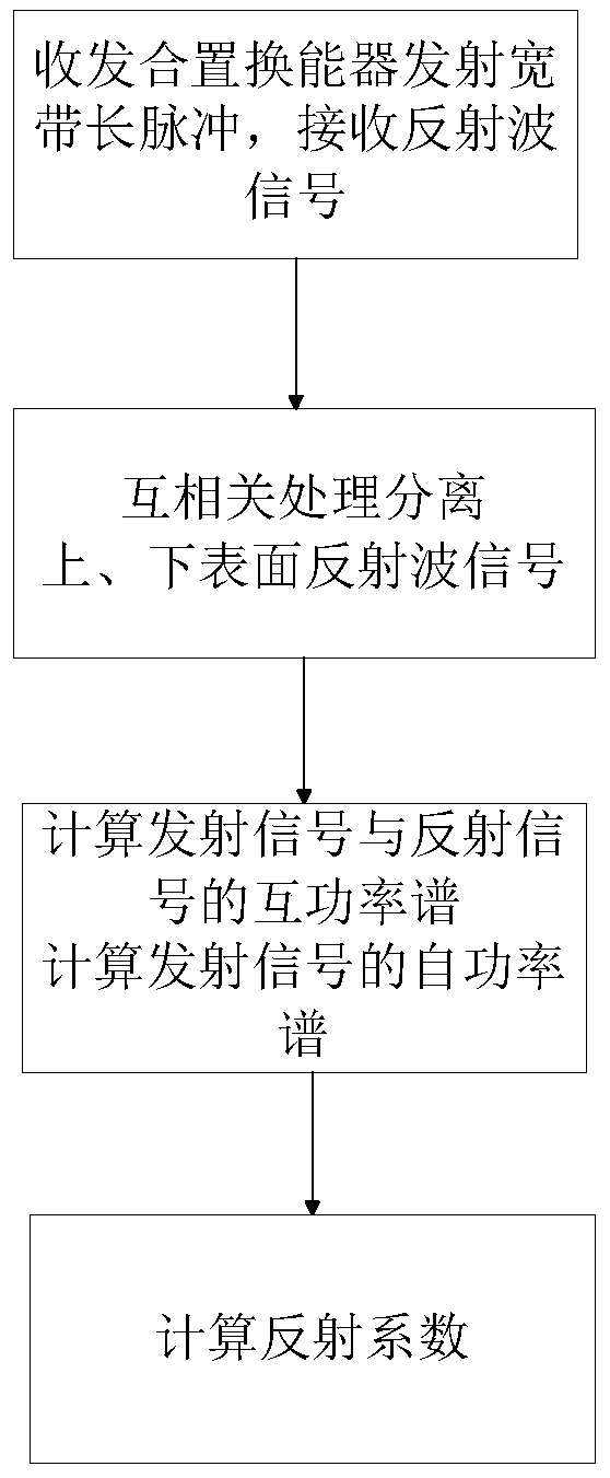
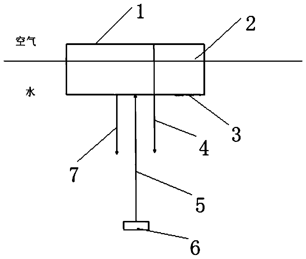
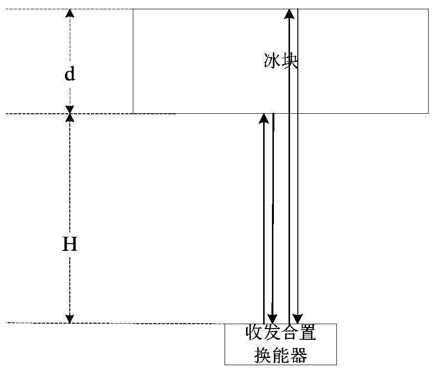
[0032] combine figure 1 , firstly, the transceiver is used to transmit long-band broadband pulse signals and then receive ice echo signals. The second step is to perform cross-correlation processing on the received echo signal and the transmitted signal. The cross-correlation processing plays the role of pulse compression. In the time domain, the reflection signals on the upper and lower surfaces of the ice layer can be separated, so that the lower The reflection signal from the surface, that is, the reflection signal from the ice-water rough surface. The third step is to calculate the cross-power spectrum of the reflected signal from the lower surface and the transmitted signal, and the self-power spectrum of the transmitted signal. The fourth step is to obtain the reflection coefficient of the lower surface by dividing the cross-power spectrum of the ...


PUM

PropertyMeasurementUnit
surface roughnessaaaaaaaaaa

Abstract

The invention provides a method for measuring a vertical sound reflection coefficient of an uneven surface of an ice layer. The method comprises the following steps: (1) emitting an emitting signal and receiving an ice layer echo signal by virtue of a receiving-emitting integrated energy converter, wherein the emitting signal is a broadband long pulse signal; (2) carrying out mutual correlation treatment on the received ice layer echo signal and emitting signal, and separating reflection signals of upper and lower surfaces of the ice layer in the time domain, so as to extract a lower surface reflection signal, namely a reflection signal of an ice-water uneven surface; (3) calculating a cross-power spectrum of the lower surface reflection signal and an auto-power spectrum of the emitting signal; and (4) dividing the cross-power spectrum of the lower surface reflection signal by the auto-power spectrum of the emitting signal, so as to obtain the reflection coefficient of the lower surface. The flexibility and universality of the method are improved; and the method can be further used for testing a surface reflection coefficient of a lamellar water sound (or air sound) material and has relatively wide application prospects.

Description

technical field [0001] The invention relates to an underwater acoustic measurement method, in particular to a vertical acoustic reflection coefficient measurement method of an underwater acoustic material. Background technique [0002] Due to natural effects such as hydrodynamics and thermodynamics, the lower surface of the ice layer is often a rough surface, and its vertical reflection coefficient is the vertical reflection coefficient of the rough surface, which often needs to be measured in actual engineering. Accurately measuring the vertical acoustic reflection coefficient of the rough lower surface of the ice layer is of great practical significance to guide the design of looking-up ice-measuring sonars. In addition, for general underwater acoustic materials, the reflection coefficient of the surface of the underwater acoustic material is the most basic acoustic parameter, especially for some underwater acoustic materials with a certain rough surface, it is often neces...

Claims


Application Information

Patent Timeline
Patent Type & Authority Patents(China)
IPC IPC(8): G01N29/04G01N29/50
Inventor 朱广平殷敬伟张天航刘强孙辉陈文剑
Owner HARBIN ENG UNIV
Learn More