
Main pump shaft seal injection water system of nuclear power plant

A technology for water injection and nuclear power plant, applied in the field of nuclear power, can solve the problems of unable to establish natural circulation, unable to realize exhaust gas, affecting the normal operation of shaft seal injection water system, etc., to optimize system structure and control, ensure safety and reliability Effect

Active Publication Date: 2019-01-15
中广核工程有限公司 +2
View PDF4 Cites 0 Cited by
  • Summary
  • Abstract
  • Description
  • Claims
  • Application Information

AI Technical Summary

Problems solved by technology

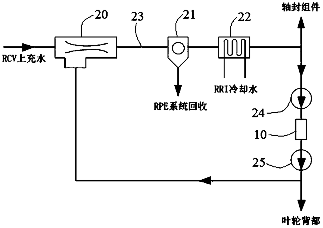
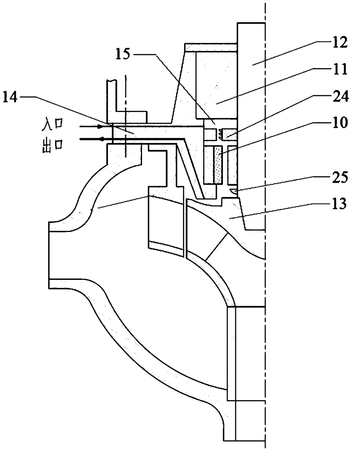
[0005] but, figure 2 and image 3 The shown shaft seal water injection system has at least the following defects: first, it cannot achieve effective exhaust, and cannot guarantee the normal operation of the system; second, two auxiliary pumps 24 and 25 need to be installed in the main pump, which increases the The complexity of the internal structure; third, when it is necessary to overhaul the jet pump 20, hydrocyclone 21 and high-pressure cooler 22, the reactor coolant cannot be effectively isolated; fourth, there is no corresponding monitoring instrument on the system loop, and it is impossible to System status is monitored; fifth, when the high-pressure cooler 22 fails, the main pump must be shut down
[0007] but, Figure 4 and Figure 5 The shaft seal water injection system shown has at least the following defects: first, the control of the shaft seal water injection system during operation is complicated, and valves 39 and 40 need to be frequently operated; second, during the main pump outage process, if At the same time, the loss of water filling on the RCV may fail to establish natural circulation, and there is a risk that the shaft seal cannot be injected with water; third, when the high-pressure cooler 31 and jet pump 30 fail, the main pump must be shut down; fourth, the valve 36 is located on the connecting pipe 33 in front of the shaft seal water injection hole of the main flange 14a. If this valve 36 fails, it will affect the normal operation of the shaft seal water injection system

Method used


Image

  • Main pump shaft seal injection water system of nuclear power plant
  • Main pump shaft seal injection water system of nuclear power plant
  • Main pump shaft seal injection water system of nuclear power plant

Examples


Embodiment Construction

[0029] In order to make the purpose, technical solution and beneficial technical effects of the present invention clearer, the present invention will be further described in detail below in conjunction with the accompanying drawings and specific embodiments. It should be understood that the specific implementations described in this specification are only for explaining the present invention, not for limiting the present invention.

[0030] see Image 6 with Figure 7 , the nuclear power plant main pump shaft seal water injection system of the present invention includes a jet pump 50, a high-pressure cooler 51, a hydrocyclone 52, a plurality of valves, connecting pipes and a pressure sensor 54 arranged outside the main pump, and a water injection system arranged inside the main pump. The auxiliary pump 55 and the internal flow passage of the main pump are connected through the shaft seal water injection hole and the high-temperature water drainage hole on the main flange 14a....


PUM


Abstract

The invention discloses a shaft seal water injection system for a main pump of a nuclear power plant, which includes a jet pump, a high-pressure cooler, a hydrocyclone, a valve, and a main connecting pipeline arranged outside the main pump, and an auxiliary pump arranged inside the main pump and the internal flow channel, the internal and external flow channels of the main pump are connected through the shaft seal water injection hole and the high-temperature water drainage hole on the main flange; the jet pump, high-pressure cooler, and hydrocyclone are arranged on the main connecting pipe in sequence; it also includes A bypass pipeline connected in parallel with the jet pump, high-pressure cooler, and hydrocyclone. The main connecting pipeline is provided with a normally open main pipeline isolation valve at both ends of the parallel section parallel to the bypass pipeline; the bypass pipeline makes the RCV The low-temperature top-fill water of the system can bypass the jet pump, high-pressure cooler, and hydrocyclone, and directly enter the shaft seal water injection hole of the main flange. Compared with the prior art, the present invention ensures the safety and reliability of system operation and the maintainability of the system through redundant design, optimized system structure and control.

Description

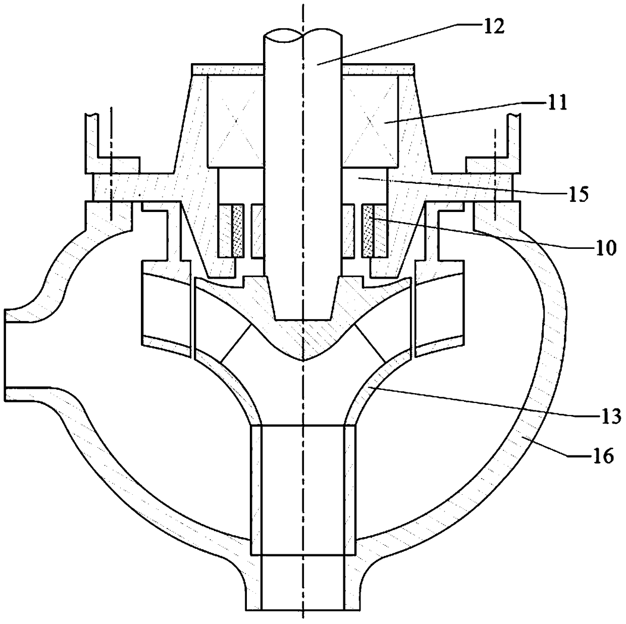
technical field [0001] The invention belongs to the field of nuclear power, and more specifically, the invention relates to a water injection system for a shaft seal of a main pump of a nuclear power plant. Background technique [0002] The reactor coolant pump is referred to as "main pump" for short, and it is one of the key equipment of the primary circuit system of the pressurized water reactor nuclear power plant. Only when the main pump operates reliably can the continuous and safe operation of the nuclear power plant be ensured. see figure 1 , The shaft-sealed main pump is provided with a water-lubricated radial bearing 10 and a shaft-seal assembly 11 on the pump body. The water-lubricated radial bearing 10 is mainly responsible for the radial force of the main pump; and the shaft seal assembly 11 ensures that the unit is under normal operating conditions and design basis accident conditions to prevent the reactor coolant from flowing along the pump shaft 12 in a cont...

Claims


Application Information

Patent Timeline
Patent Type & Authority Patents(China)
IPC IPC(8): F04D29/10F04D15/00F04D29/06F04D29/58
CPCF04D15/00F04D29/061F04D29/106F04D29/5886F04D7/08F04D29/588G21C15/243G21D1/04Y02E30/30Y02E30/00F04D29/10F16J15/162F16J15/3404F16J15/16F16J15/34G21D1/02
Inventor 陈兴江罗志远段远刚李中双符伟丛国辉陈瞾宋小伍刘彦章王学灵马家炯张翊勋
Owner 中广核工程有限公司
Learn More