A horizontal enthalpy increasing compressor

A compressor and horizontal technology, applied in the field of horizontal enthalpy increasing compressors, can solve the problems of high height and large volume, and achieve the effects of reducing costs, miniaturizing the structure, and facilitating processing and assembly.

Active Publication Date: 2019-07-30
ZHUHAI LANDA COMPRESSOR +1
View PDF6 Cites 0 Cited by
  • Summary
  • Abstract
  • Description
  • Claims
  • Application Information

AI Technical Summary

Problems solved by technology

[0004] Therefore, the technical problem to be solved by the present invention is to overcome the defects of high height and large volume of the horizontal compressor in the prior art, so as to provide a horizontal enthalpy-increasing compressor

Method used


Image

  • A horizontal enthalpy increasing compressor
  • A horizontal enthalpy increasing compressor
  • A horizontal enthalpy increasing compressor

Examples


Embodiment 1

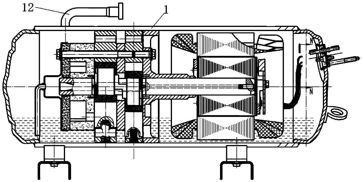
[0030] like Figure 3-6 As shown, the present invention provides a horizontal enthalpy increasing compressor, which includes a casing 1 and an upper flange 2 arranged in the casing 1 along the axial direction of the casing 1, an upper cylinder 3, and a partition 4. Lower cylinder 5, lower flange 6 and lower cover plate 7, (such as Figure 4 As shown, the upper flange 2, the upper cylinder 3, the separator 4, the lower cylinder 5, the lower flange 6 and the lower cover plate 7 are arranged in sequence along the axial direction, that is, they are arranged in sequence from right to left in the figure) The flange 6 has a medium-pressure chamber 8 communicating with the air inlet of the lower cylinder 5, and also includes an enthalpy-increasing air supply pipe 9, and the enthalpy-increasing air supply pipe 9 passes through the lower cover plate 7 from the outside of the compressor It penetrates into the interior of the compressor (medium-pressure chamber 8), and is used to repleni...

Embodiment 2

[0038] like Figure 4, as shown in 7-8, this embodiment is a further improvement made on the basis of embodiment 1, preferably, it also includes an exhaust pipe 12, and the exhaust pipe 12 passes from the outside of the compressor through the The lower cover plate 7 penetrates into the compressor and is used for exhausting the compressor. By penetrating the exhaust pipe from the outside of the compressor into the interior of the compressor through the lower cover plate, it is used to exhaust the compressor. In terms of exhausting to the outside of the compressor, the exhaust pipe is effectively arranged on the lower cover plate on the lateral side of the horizontal compressor, so that the horizontal compressor can be effectively reduced while protruding upwards. The height of the top of the compressor effectively reduces the volume of the compressor, making the structure more miniaturized, simple in structure, easy to produce in batches, and reduces the cost; the invention ad...


PUM


Abstract

The invention provides a horizontal type enthalpy-increasing compressor. The horizontal type enthalpy-increasing compressor comprises a housing (11) as well as an upper flange (2), an upper air cylinder (3), a partition (4), a lower air cylinder (5), a lower flange (6) and a lower cover plate (7) which are arranged in the housing (1) in the axial direction of the housing (1), and further comprises a enthalpy-increasing gas-supplementing tube (9), wherein the lower flange (6) is provided with a medium-pressure cavity (8) which communicates with a gas inlet of the lower air cylinder (5); the gas-supplementing tube (9) penetrates into the compressor via the lower cover plate (7) from the outer part of the compressor for performing gas-supplementing enthalpy-increasing on the compressor. Compared with the horizontal type compressor in the prior art, the horizontal type enthalpy-increasing compressor has the advantage that the gas-supplementing enthalpy-increasing tube is arranged on the lower cover plate on the transverse side surface of the horizontal type compressor, integral top height of the horizontal type compressor can be effectively reduced while the horizontal type compressor extends out upwards, the size is reduced, the structure is smaller and is simple, batch production is easy and cost is reduced.

Description

technical field [0001] The invention belongs to the technical field of air conditioning, and in particular relates to a horizontal enthalpy-increasing compressor. Background technique [0002] Existing horizontal compressor enthalpy-increasing pipes (the corresponding enthalpy-increasing suction pipes are arranged on the cylinder or the lower flange) and exhaust pipes are all arranged on the shell, and the enthalpy-increasing passages are all from the shell through the cylinder or the flange. Lan into the pump body. As a result, the design and processing of the cylinder and flange are more complicated. At the same time, because the height of some air-conditioning systems is limited, the enthalpy-increasing pipes and exhaust pipes are installed on the shell, which cannot meet the smaller height requirements of the air-conditioning system, as follows figure 1 and figure 2 shown. [0003] Because the horizontal compressor in the prior art has technical problems such as hig...

Claims


Application Information

Patent Timeline
Patent Type & Authority Patents(China)
IPC IPC(8): F04C29/12F04C29/00
CPCF04C29/00F04C29/12F04C2240/806
Inventor 吕浩福郑坚标
Owner ZHUHAI LANDA COMPRESSOR
Why Eureka
Try Eureka