
Improved refrigerator hinge

A technology for hinges and refrigerators, applied to hinges with pins, switches with brakes, hinge plates, etc., can solve the problems of difficulty in ensuring assembly strength, low assembly efficiency, affecting use performance, etc., and achieve a stable assembly structure. Reliable, convenient and easy switching operation, and the effect of simplifying the assembly process

Inactive Publication Date: 2017-06-20
JIANGSU SACA PRECISION TECH CO LTD
View PDF8 Cites 4 Cited by
  • Summary
  • Abstract
  • Description
  • Claims
  • Application Information

AI Technical Summary

Problems solved by technology

Yet present refrigerator hinge has the following disadvantages: 1. The elastic buffer is arranged in the rear transmission arm, which is pushed to work by the boss on the hinge seat. When the rear transmission arm rotates, the rotating shaft of the boss is always in a fixed state, thereby pressing When the spring is affected by the radial stress, the spring is prone to radial deformation and uneven force; 2. The positioning piece and the fixing seat are set separately, and the fixing seat can only be fixed on the refrigerator frame through the positioning piece. Not only does it result in low assembly efficiency due to many assembly processes, but it is also difficult to ensure the assembly strength, and it may be loose due to errors, which affects the performance of use; 3. The hinge seat rotates less force arm, resulting in a larger thrust required for the refrigerator door to rotate , it is not easy to operate, and there are many connection points inside the hinge, which may easily lead to the accumulation of water vapor, dirt, etc.

Method used


Image

  • Improved refrigerator hinge
  • Improved refrigerator hinge
  • Improved refrigerator hinge

Examples


Embodiment Construction

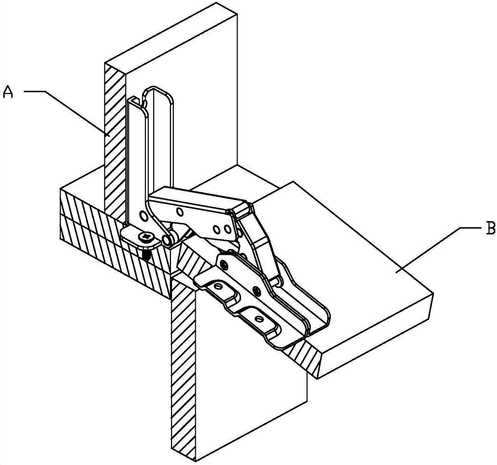
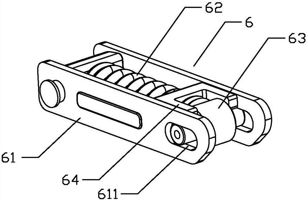
[0022] The present invention will be further described below in conjunction with accompanying drawing, according to Figure 1-Figure 4 As shown, the improved refrigerator hinge of the present invention includes a fixed seat 1 fixed on the refrigerator frame A, a hinge seat 2 fixed on the refrigerator door B, and a hinge arranged between the fixed seat 1 and the hinge seat 2 Assembly; the hinge assembly includes the first transmission arm 3, the second transmission arm 4, the rear transmission arm 5 and the lower transmission arm; one end of the first transmission arm 3 is hinged to the bending part of the fixed seat 1, and the other end of the first transmission arm 3 is hinged with a buffer Head 7, one end of the rear transmission arm 5 is fixedly connected to the buffer head 7, the other end of the rear transmission arm 5 is hinged to the middle part of the hinge seat 2, one end of the second transmission arm 4 is hinged to the end of the fixing seat 1, and the other end of t...


PUM


Abstract

The invention provides an improved refrigerator hinge. The improved refrigerator hinge comprises a fixing seat, a hinge seat and a hinge assembly arranged between the fixing seat and the hinge seat. The hinge assembly comprises a first transmission arm, a second transmission arm, a rear transmission arm and a lower transmission arm. One end of the first transmission arm is hinged to the fixing seat, and the other end of the first transmission arm is hinged to a buffering head. One end of the rear transmission arm is connected with the buffering head, and the other end of the rear transmission arm is hinged to the hinge seat. One end of the second transmission arm is hinged to the fixing seat, and the other end of the second transmission arm is hinged to the rear transmission arm. One end of the lower transmission arm is hinged to the second transmission arm, and the other end of the lower transmission arm is hinged to the hinge seat. The first transmission arm is provided with an elastic buffering device. The buffering head acts on the buffering end of the elastic buffering device for linear buffering. One or more assembling plates are integrally formed on the fixing seat. In the hinge starting state, the second transmission arm stretches across the fixing seat and the hinge seat. The improved refrigerator hinge is stable and reliable in performance, stable and reliable in structure and capable of effectively preventing water, dirt and the like from being accumulated.

Description

technical field [0001] The invention relates to a hinge transmission part, in particular to an improved refrigerator hinge. Background technique [0002] Refrigerator hinges are currently the most commonly used connectors for turning and opening refrigerator doors. In order to achieve a good closing performance between the refrigerator door and the refrigerator cabinet after opening or closing, the existing refrigerator hinges usually use six connecting rods. transmission mechanism. Yet present refrigerator hinge has the following disadvantages: 1. The elastic buffer is arranged in the rear transmission arm, which is pushed to work by the boss on the hinge seat. When the rear transmission arm rotates, the rotating shaft of the boss is always in a fixed state, thereby pressing When the spring is affected by the radial stress, the spring is prone to radial deformation and uneven force; 2. The positioning piece and the fixing seat are set separately, and the fixing seat can on...

Claims


Application Information

Patent Timeline
Patent Type & Authority Applications(China)
IPC IPC(8): E05D11/00E05F5/08E05D5/02E05D3/06F25D23/02
CPCE05D3/06E05D5/02E05D11/00E05F5/08E05Y2900/31F25D23/028E05D3/16E05F1/1253E05Y2900/306F25D2323/024E05D5/0215E05Y2600/632
Inventor 蔡耿锡张翔黄河生杨文明
Owner JIANGSU SACA PRECISION TECH CO LTD
Learn More