
Support suspension system and electric car

A technology for suspension systems and electric vehicles, which is applied in the direction of electric power devices, power devices, vehicle components, etc., and can solve problems such as poor safety of high-voltage electrical components

Inactive Publication Date: 2017-06-20
FAFA AUTOMOBILE (CHINA) CO LTD
View PDF0 Cites 6 Cited by
  • Summary
  • Abstract
  • Description
  • Claims
  • Application Information

AI Technical Summary

Problems solved by technology

[0004] In view of this, the present invention provides a support suspension system and an electric vehicle to solve the problem of poor safety of high-voltage electrical components in current electric vehicles under collision conditions

Method used


Image

  • Support suspension system and electric car
  • Support suspension system and electric car
  • Support suspension system and electric car

Examples


Embodiment 1

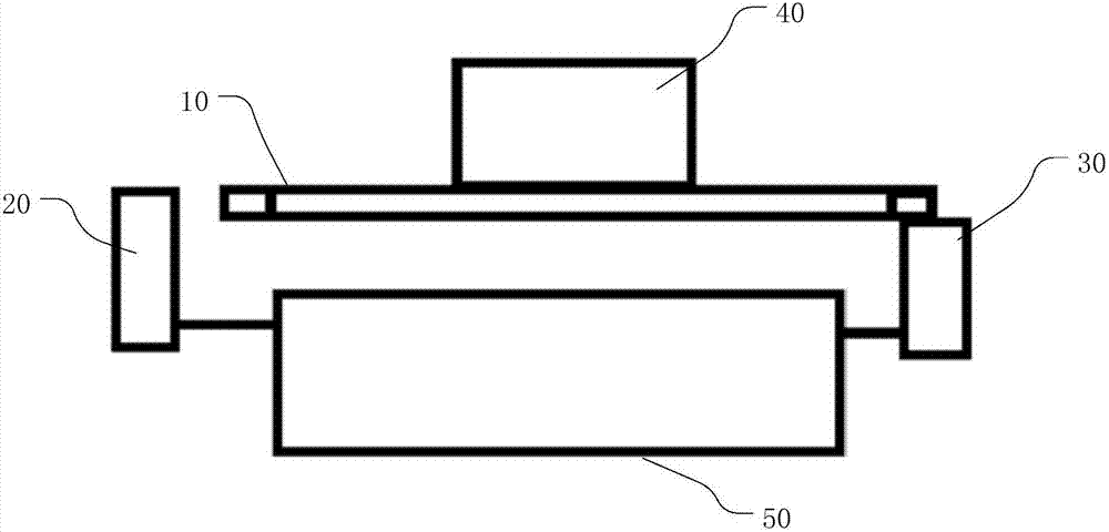
[0029] figure 1 It is a structural schematic diagram of an embodiment of a support suspension system provided by the present invention.

[0030] The support and suspension system provided in this embodiment is applied to an electric vehicle, and is specifically arranged in an engine compartment of the electric vehicle. This kind of electric vehicle is a pure electric vehicle driven purely by electricity, so facilities such as drive motors and high-voltage electrical components are arranged in the engine compartment. And there is a vehicle body longitudinal beam (not shown) which supports the vehicle body in the electric vehicle, and the vehicle body longitudinal beam includes a left longitudinal beam on the left side and a right side beam on the right side.

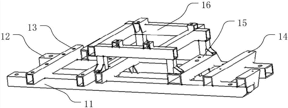
[0031] The body longitudinal beam is the key part of the frame, and the frame is the most important load-bearing part in the car, so the body longitudinal beam plays an important role in the car. The side beam frame of t...

Embodiment 2

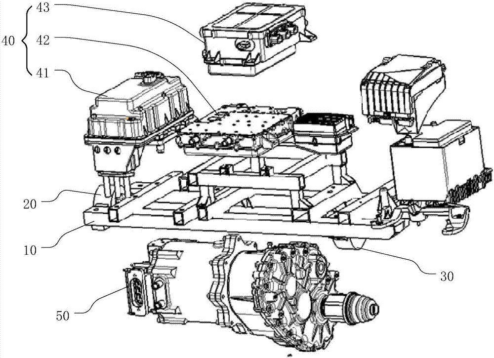
[0044] This embodiment also provides an electric vehicle, the electric vehicle includes the supporting suspension system provided in the above embodiment, and the system is used to carry the high-voltage electrical components and the driving motor of the electric vehicle. The system specifically includes motor left mount, motor right mount and electrical bracket. The two ends of the electrical bracket are respectively fixed on the left longitudinal beam and the right longitudinal beam; the high-voltage electrical parts are fixed on the upper part of the electrical bracket; the left suspension of the motor is fixed on the left longitudinal beam; the right suspension of the motor is fixed on the electrical bracket One end fixed to the right longitudinal beam; the two ends of the driving motor are respectively fixed on the left motor mount and the motor right mount, and are located below the electrical bracket. Generally speaking, the strength of the drive motor is the highest, f...


PUM


Abstract

The embodiment of the invention provides a support suspension system and an electric car, and is applied to carrying high-voltage electric components and a drive motor of the electric car. The system comprises a motor left suspension mount, a motor right suspension mount and an electrical bracket. The two ends of the electrical bracket are respectively fixed on a left longitudinal beam and a right longitudinal beam; the high-voltage electrical component is fixed on the upper part of the electrical bracket; the motor left suspension mount is fixed on the left longitudinal beam; the motor right suspension mount is fixed on the fixed end of the electrical bracket with the right longitudinal beam; the two ends of the drive motor are respectively fixed on the motor left suspension mount and the motor right suspension mount and are located below the electrical bracket. When a collision occurs, part of the force spread through the motor left suspension mount, the drive motor and the motor right suspension mounts, the force borne by the drive motor decreases the adverse effects on high-voltage electrical components, so that in the event of collisions the high-voltage electrical components can be well protected, so as to resolve the issue of poor safety of the high-voltage electrical components in current electric cars when in collisions.

Description

technical field [0001] The invention relates to the technical field of electric vehicles, in particular to a support suspension system and the electric vehicle. Background technique [0002] Compared with traditional internal combustion engine vehicles, in addition to using electric motors instead of internal combustion engines in the engine compartment of electric vehicles driven purely by electricity, high-voltage electrical components such as inverters, high-voltage power distribution units, and chargers must also be arranged. Safety under these conditions is very important. [0003] In the process of implementing the present application, the inventor found that in the existing layout of the engine compartment of electric vehicles, the collision safety of high-voltage electrical components is mainly guaranteed by their respective mounting brackets, suspension cushions, etc. Considering the project as a whole, we often lose sight of the other. Specifically, the left and ...

Claims


Application Information

Patent Timeline
Patent Type & Authority Applications(China)
IPC IPC(8): B60K1/00B62D21/00
CPCB60K1/00B62D21/00
Inventor 杨连松赵荣远李志平卢元甲
Owner FAFA AUTOMOBILE (CHINA) CO LTD
Learn More