Printing numerically-controlled flame cutting machine

A flame cutting machine and flame cutting technology, applied in the direction of gas flame welding equipment, welding equipment, metal processing, etc., can solve the problem that the oxygen acetylene tube cannot be adapted to the on-site installation and operation, affects the progress of the cutting and blanking process, and cannot be used normally. problems, to achieve the effect of saving reclaiming time, prolonging the service life and improving the safety of use

Inactive Publication Date: 2017-06-20
安徽恒源煤电股份有限公司
View PDF0 Cites 0 Cited by
  • Summary
  • Abstract
  • Description
  • Claims
  • Application Information

AI Technical Summary

Problems solved by technology

The original hand-held gas cutting torch and portable CNC cutting machine have slow cutting speed and low precision, which seriously affect the progress of the cutting and blanking process.
However, with the printing CNC flame cutting machine, problems such as the laying of the cutting machine track, the design of the support frame, and the placement of the oxygen acetylene tube cannot meet the needs of on-site installation and operation, so it cannot be used normally.

Method used


Image

  • Printing numerically-controlled flame cutting machine
  • Printing numerically-controlled flame cutting machine

Examples


Embodiment 1

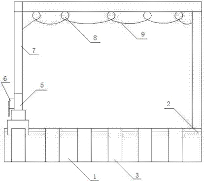
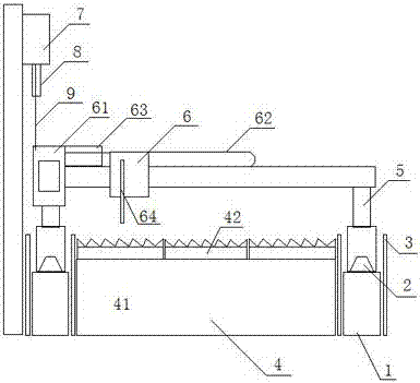
[0015] Such as figure 1 A printing type numerical control flame cutting machine shown includes two cutting machine tracks 2 laid in parallel, and a laying platform 1 is installed under each track, and the lower part of the laying platform 1 is fixed on the ground; The plate 3 and the protective plate 3 are higher than the cutting machine track 2; the cutting table 4 includes a cutting bench and several zigzag strip groups 42 installed on the cutting bench 41; the welding beam frame 5 is arranged on two cutting machine rails 2 , the flame cutting assembly 6 is installed on the crossbeam of the welded beam frame, at the air inlet end of the flame cutting assembly 6, a hanger 7 is set on the side parallel to the track 2 of the cutting machine, a pulley block 8 is arranged on the hanger 7, and the air pipe 9 is connected to the pulley block 8 .

[0016] The zigzag slat group 42 is composed of a plurality of zigzag slats arranged in parallel and at intervals.

[0017] The flame c...

Embodiment 2

[0021] A print-type numerical control flame cutting machine, including a self-made cutting machine track platform, using two 32# I-beams with a length of 6 meters and a gauge of 3 meters, placed in parallel, as a laying platform for the cutting machine track. In order to achieve the purpose of stabilizing the track laying platform, the upper and lower parts of the I-beam are welded to steel plates with a length of 6 meters, a width of 120 mm, and a thickness of 20 mm. The upper plane is milled with a milling machine to ensure flatness. A number of holes with a diameter of 20 mm are drilled on the lower plane and fixed on the ground with expansion bolts.

[0022] Considering that the lifting steel plate will hit the track of the cutting machine, causing track damage and affecting the normal use of the cutting machine, 6 pieces of 350x200x10 mm steel plates are welded on the outside of the two track platforms, with a spacing of 800 mm and the upper end protruding 150 mm; The inn...


PUM


Abstract

The invention discloses a printing-type numerical control flame cutting machine, which comprises two cutting machine tracks laid in parallel, a laying platform is installed under each track, and the lower part of the laying platform is fixed on the ground; protective plates are arranged on both sides of the laying platform to protect the The plate is higher than the cutting machine track; the cutting table includes the cutting table frame and several sawtooth-shaped strip groups installed on the cutting table frame; the welding beam is erected on the two cutting machine tracks, and the flame cutting assembly is installed on the beam of the welding beam frame , at the inlet end of the flame cutting assembly, a hanger is set on the side parallel to the track of the cutting machine, a pulley block is set on the hanger, and the air pipe is connected to the pulley block. The invention is more stable, prolongs the service life of the track, avoids the damage caused by the friction and winding of the trachea, prolongs the service life of the trachea, can cut plates of various sizes and shapes, is convenient to take, saves the time for taking materials, and improves work efficiency 20%.

Description

technical field [0001] The invention relates to a numerically controlled flame cutting machine, in particular to a printing type numerically controlled flame cutting machine. Background technique [0002] With the increase in the specifications and types of tape machines designed and produced by the mechanical and electrical repair institute, the one-time forming, cutting and blanking work of steel plates will increase accordingly. At this time, the improvement of work efficiency is particularly important. The original hand-held gas cutting gun and portable CNC cutting machine had slow cutting speed and low precision, which seriously affected the progress of the cutting and blanking process. However, with the printing-type CNC flame cutting machine, problems such as the laying of the cutting machine track, the design of the support frame, and the placement of the oxygen acetylene tube cannot meet the needs of on-site installation and operation, so it cannot be used normally....

Claims


Application Information

Patent Timeline
Patent Type & Authority Applications(China)
IPC IPC(8): B23K7/00B23K7/10
CPCB23K7/00B23K7/10B23K2101/18
Inventor 刘世方王峰
Owner 安徽恒源煤电股份有限公司
Why Eureka
Try Eureka