Special-shaped section metal hollow component six-axis free bending forming device and technology analysis method

A technology for hollow components and special-shaped cross-sections, which is applied in the field of six-axis free bending forming equipment for hollow components with special-shaped cross-sections, and can solve the problems of flat cross-sections, limited degrees of freedom, and labor and material resources.

Active Publication Date: 2017-06-20
NANJING UNIV OF AERONAUTICS & ASTRONAUTICS
View PDF5 Cites 16 Cited by
  • Summary
  • Abstract
  • Description
  • Claims
  • Application Information

AI Technical Summary

Problems solved by technology

When the above-mentioned parts are formed by the method of internal high pressure forming, the production efficiency is low and the cost is high due to the need for mold opening, repeated mold trial, and mold repair.
However, when the above-mentioned parts are formed by using methods such as stretch bending, press bending, and roll bending, on the one hand, the spatial geometry of the parts that can be formed is relatively simple, which is difficult to meet the forming requirements of complex three-dimensional axis space parts. Parts are prone to defe

Method used


Image

  • Special-shaped section metal hollow component six-axis free bending forming device and technology analysis method
  • Special-shaped section metal hollow component six-axis free bending forming device and technology analysis method
  • Special-shaped section metal hollow component six-axis free bending forming device and technology analysis method

Examples


Embodiment 1

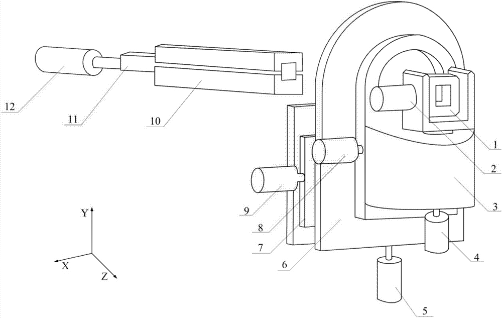
[0097] Step 1), reference figure 2 , for the square tube to be bent, feed the material horizontally at a speed of 10mm / s, start the equipment X-axis motor (9), and make the bending die (1) produce an eccentricity of 1mm in the X-axis direction. Continue to feed the material to obtain the bending radius of the square tube when the eccentricity is 1 mm. Repeat the test to obtain the bending radius of the square tube when the eccentricity is 2mm, 3mm, 4mm, 5mm, 6mm..., and then obtain a series of relationship points between the eccentricity and the bending radius for the square tube;

[0098] In step 2), a series of points obtained in step 1) are fitted to obtain a relationship curve between eccentricity and bending radius for the specific square tube.

[0099] Step 3), will be as figure 2 The three-dimensional geometric model of the square pipe shown is segmented, including straight and curved segments;

[0100] Step 4), obtain the first straight section of the square tube ...

Embodiment 2

[0127] Step 1), reference image 3 , for the I-shaped cross-section profile to be bent, feed the material horizontally at a speed of 10mm / s, start the X-axis movement motor of the equipment, and make the bending die produce an eccentricity of 1mm in the X-axis direction. Continue to feed the material to obtain the bending radius of the I-shaped cross-section profile when the eccentricity is 1 mm. Repeat the test to obtain the bending radius of the I-shaped section profile when the eccentricity is 2mm, 3mm, 4mm, 5mm, 6mm..., and then obtain a series of relationship points between the eccentricity and the bending radius for the I-shaped section ;

[0128] In step 2), a series of points obtained in step 1) are fitted to obtain a relationship curve between the eccentricity and the bending radius of the specific I-shaped cross-section profile.

[0129] Step 3), will be as image 3 The three-dimensional geometric model of the shown I-shaped section bar is segmented, including the...

Embodiment 3

[0157] Step 1), for the to be bent such as Figure 4 The special-shaped cross-section pipe shown is fed horizontally at a speed of 10mm / s, and the X-axis movement motor of the equipment is started to make the bending die produce an eccentricity of 1mm in the X-axis direction. Continuously feed the material to obtain the bending radius of the special-shaped cross-section pipe when the eccentricity is 1 mm. Repeat the test to obtain the bending radius of the special-shaped cross-section pipe when the eccentricity is 2mm, 3mm, 4mm..., and then obtain a series of relationship points between the eccentricity and the bending radius for the special-shaped cross-section pipe;

[0158] Step 2): Fitting a series of points obtained in step 1) to obtain a relationship curve between the eccentricity and the bending radius for the pipe with special-shaped cross-section.

[0159] Step 3), will be as Figure 4 The three-dimensional geometric model of the special-shaped cross-section pipe sh...


PUM


Abstract

The invention discloses a special-shaped section metal hollow component six-axis free bending forming device and a technology analysis method. The special-shaped section metal hollow component six-axis free bending forming device comprises following multi-axis motion systems including an X-axis motion system, a Y-axis motion system, a Z-axis feeding system, a bending die Y-axis surrounding rotation system, a bending die Z-axis surrounding rotation system and a bending die axis surrounding pitching swinging system. The X-axis motion system comprises an X-axis motor (9) and an X-axis motion mechanism (7). The Y-axis motion system comprises a Y-axis motor (5) and a Y-axis motion mechanism (6). The Z-axis feeding system comprises a Z-axis motor (12), a guiding mechanism (10) and a feeding mechanism (11). The bending die Y-axis surrounding rotation system comprises a Y-axis rotation motor (4). The bending die Z-axis surrounding rotation system comprises a Z-axis surrounding rotation motor (8) and a Z-axis surrounding rotation mechanism (3). The bending die axis surrounding pitching swinging system comprises a bending die (1) and a bending die swinging motor (2). The invention further provides a forming method applying the above six-axis special-shaped section hollow component free bending forming device. By means of the special-shaped section metal hollow component six-axis free bending forming device and the forming method, high-size precision and small-section-deformation high-quality forming of a special-shaped section hollow component can be achieved.

Description

technical field [0001] The invention belongs to the technical field of advanced manufacturing of metal complex components, and in particular relates to six-axis free bending forming equipment and a process analysis method for hollow components with special-shaped cross-sections. Background technique [0002] Hollow components with rectangular cross-section or special-shaped cross-section are mainly used as load-bearing components in aviation, aerospace or automotive fields, such as special-shaped pipe fittings for automobile exhaust systems, automobile sub-frames, instrument panel brackets, body frames and hollow shafts, complex pipes, etc. . The traditional forming methods of such parts mainly include: internal high pressure forming, stretch bending, press bending, roll bending, etc. When the above-mentioned parts are formed by the method of internal high pressure forming, due to the need for mold opening, repeated mold trial, mold repair and other processes, the productio...

Claims


Application Information

Patent Timeline
IPC IPC(8): B21D7/00
CPCB21D7/00
Inventor 郭训忠马燕楠王辉陶杰熊昊靳凯
Owner NANJING UNIV OF AERONAUTICS & ASTRONAUTICS
Why Eureka
Try Eureka