
Air conditioner system and refrigeration control method and device

A technology of air conditioning system and refrigeration cycle, applied in air conditioning system, refrigeration and liquefaction, control input involving air characteristics, etc., can solve the problem of unadjustable refrigerant flow rate of pumps and compressors, poor system reliability, and unfavorable system energy saving and other problems, to achieve the effect of reducing air-conditioning energy consumption, improving work reliability, and improving the annual energy efficiency ratio

Active Publication Date: 2017-06-16
EMERSON NETWORK POWER CO LTD
View PDF16 Cites 7 Cited by
  • Summary
  • Abstract
  • Description
  • Claims
  • Application Information

AI Technical Summary

Problems solved by technology

[0004] The disadvantage of the existing technology is that the operation time of the pump mode is relatively short throughout the year, which makes little contribution to the improvement of the annual energy efficiency ratio; the refrigerant flow rate of the pump and compressor cannot be adjusted, which is not conducive to energy saving of the system; in addition , in the above system, if the refrigerant pipeline fails, such as refrigerant leakage, neither the compressor mode nor the pump mode can operate, resulting in poor system reliability

Method used


Image

  • Air conditioner system and refrigeration control method and device
  • Air conditioner system and refrigeration control method and device
  • Air conditioner system and refrigeration control method and device

Examples


Embodiment 1

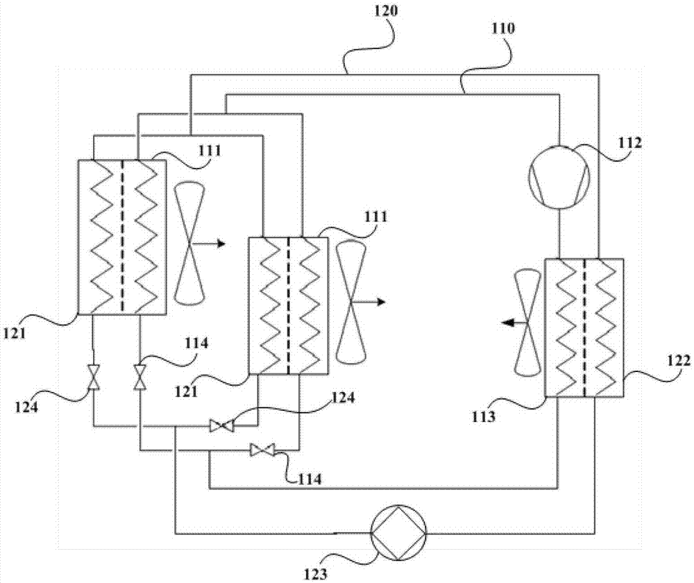
[0078] Such as figure 2 As shown, the air conditioning system provided by the first embodiment of the present invention includes at least one first refrigeration cycle loop 110 and at least one second refrigeration cycle loop 120. The first refrigeration cycle loop 110 includes first evaporators connected in sequence and forming a closed cycle. The device element 111, the compressor 112, the first condenser element 113 and the first throttle valve 114; the second refrigeration cycle circuit 120 includes the second evaporator element 121, the second condenser element 122, the second condenser element 122, pump 123 and second throttle valve 124; wherein:

[0079] The first evaporator element 111 in the first refrigeration cycle 110 and the second evaporator element 121 in the second refrigeration cycle 120 form a compound evaporator, and the first evaporator element 111 is located on the air outlet side of the compound evaporator. The second evaporator element 121 is located o...

Embodiment 2

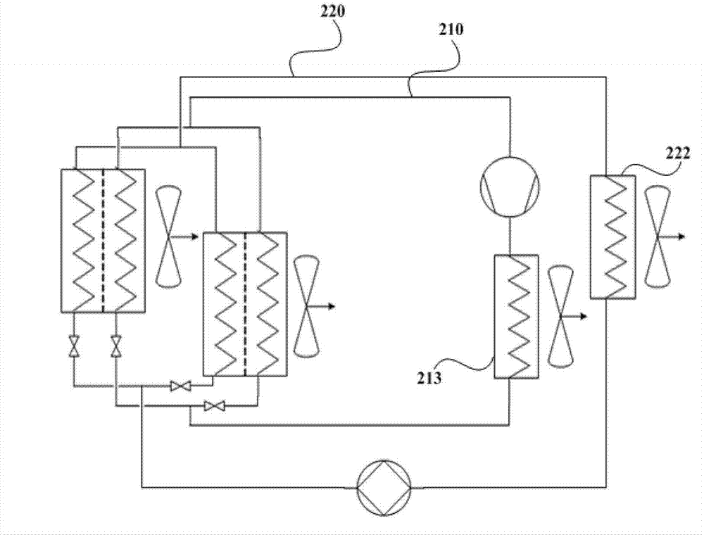
[0095] Such as image 3 As shown, the structure of the air-conditioning system of this embodiment, compared with the structure of the air-conditioning system of Embodiment 1, differs in that:

[0096] The first condenser element 213 in the first refrigeration cycle 210 and the second condenser element 222 in the second refrigeration cycle 220 are distributed. In this way, the configuration requirements of different refrigeration cycle circuits can be met, and the configuration mode is more flexible.

Embodiment 3

[0098] Such as Figure 4 As shown, the structure of the air-conditioning system of this embodiment, compared with the structure of the air-conditioning system of Embodiment 2, differs in that:

[0099] The first refrigeration cycle circuit 310 further includes: an auxiliary pump 315 located between the first condenser element 313 and the first throttle valve 314 , and a bypass valve 316 arranged in parallel with the compressor 312 .

[0100] When the outdoor temperature is low enough, the first refrigeration cycle 310 does not work, and the second refrigeration cycle 320 is used to provide the required cooling capacity; but when the outdoor temperature is low but not low enough, the second refrigeration cycle 320 is not enough Provide the required cooling capacity, at this time, still close the compressor 312, open the bypass valve 316, the cooling capacity provided by the refrigeration cycle circuit where the pump 323 is located is used for the first cooling of the return air...


PUM


Abstract

The invention discloses an air conditioner system and a refrigeration control method and device to increase the annual energy efficiency ratio of an air conditioner, reduce energy consumption of the air conditioner and improve work reliability of the air conditioner. The air conditioner system comprises at least one first refrigeration circulating loop and at least one second refrigeration circulating loop, each first refrigeration circulating loop comprises a first evaporator element, a compressor, a first condenser element and a first throttle valve which are sequentially connected to form closed circulation, and each second refrigeration circulating loop comprises a second evaporator element, a second condenser element, a pump and a second throttle valve which are sequentially connected to form closed circulation; the first evaporator elements in the first refrigeration circulating loops and the second evaporator elements in the second refrigeration circulating loops form a combined evaporator, the first evaporator elements are located at the air outlet side of the combined evaporator, and the second evaporator elements are located at the air inlet side of the combined evaporator.

Description

technical field [0001] The invention relates to the technical field of refrigeration equipment, in particular to an air conditioning system, a refrigeration control method and a device. Background technique [0002] With the development of modern information technology, the number and scale of communication equipment rooms across the country are also expanding. Under the call of the national energy conservation and emission reduction policy, reducing energy consumption in computer rooms has become the focus of many operators. According to the survey, in the computer room, the power consumption of the precision air conditioner alone accounts for more than 50% of the total electricity consumption of the computer room. In a large number of base stations and module bureaus, the power consumption of air conditioners can reach about 70% of the total power consumption of the base stations or module bureaus. Therefore, effectively reducing the power consumption of air conditioners...

Claims


Application Information

Patent Timeline
Patent Type & Authority Applications(China)
IPC IPC(8): F24F5/00F24F11/00F25B49/02F25B5/00
CPCF24F5/001F24F11/30F24F11/62F24F11/70F24F2110/10F25B5/00F25B49/022F24F2110/12F24F11/65F25B2600/25F25B2600/024Y02B30/70
Inventor 梁婷谯峤万积清
Owner EMERSON NETWORK POWER CO LTD
Learn More