
Filling valve for preventing dripping leakage

A filling valve, anti-drip technology, applied in packaging, bottle filling, liquid bottling, etc., can solve the problems of difficult to achieve accurate filling, equipment corrosion damage, waste, etc., to achieve good precision control, good sealing effect, Guarantee the effect of production rhythm

Pending Publication Date: 2020-01-07
JIANYANG CHENGCHUANG PACKAGING MACHINERY
View PDF0 Cites 4 Cited by
  • Summary
  • Abstract
  • Description
  • Claims
  • Application Information

AI Technical Summary

Problems solved by technology

In practical application, after the pneumatic angle valve in the traditional filling valve is closed, some materials will still remain on the inner wall of the filling rod, which will flow down the inner wall of the filling rod and drip to the outer wall of the container or the conveying line. At the same time, due to the above-mentioned dripping situation, the closing of the pneumatic angle valve cannot realize timely cut-off, and some materials will still flow into the container, causing filling failure. errors, it is difficult to achieve accurate filling; in addition, dripping materials will also cause a lot of waste
In order to solve the problem of dripping of the filling valve, there is also a back-suction filling valve in the prior art. The excess material is sucked back by setting a vacuum pump. However, it is difficult to refill these back-suction materials, and there is still a problem of waste. , and the material sucked back will enter the vacuum pump and cause corrosion damage to the equipment, which is not practical in actual production

Method used


Image

  • Filling valve for preventing dripping leakage
  • Filling valve for preventing dripping leakage
  • Filling valve for preventing dripping leakage

Examples


Embodiment Construction

[0027] The technical solution of the present invention will be further described in detail below in conjunction with the accompanying drawings, but the protection scope of the present invention is not limited to the following description.

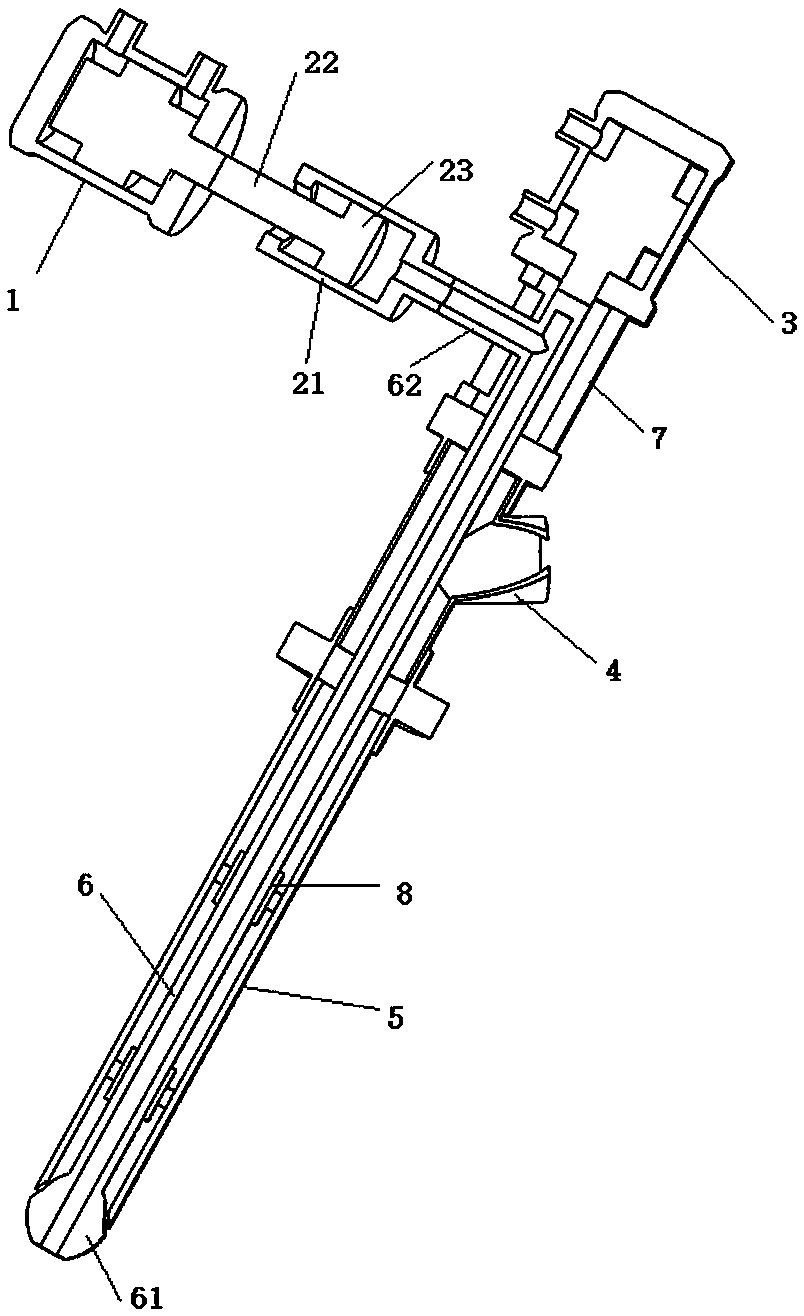
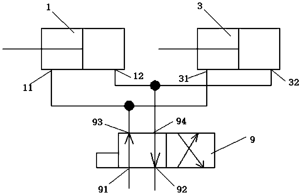
[0028] like figure 1 , figure 2 As shown, a drip-proof filling valve includes a cylinder a1, a cylinder piston mechanism 2, a cylinder b3, a filling rod 5, a valve stem 6 and a feed pipe 4. Wherein the filling rod 5 is a hollow cylindrical structure, the valve rod 6 is axially movable and arranged in the filling rod 5, and one end of the valve rod 6 is provided with a sealing head 61 which is sealingly adapted to one end of the filling rod 5, The other end of the filling rod 5 is sealingly adapted to the rod body of the valve rod 6, and the end of the valve rod 6 away from the sealing head 61 is fixedly connected to the telescopic rod end of the cylinder b3. The outer wall of the filling rod 5 is connected with a feed pipe 4 communicatin...


PUM


Abstract

The invention discloses a filling valve for preventing dripping leakage, and relates to the field of filling equipment. The filling valve comprises a cylinder barrel piston mechanism, a filling rod and a valve rod. The filling rod and the valve rod are of hollow cylinder structures, the valve rod can be arranged in the filling rod in an axial moving manner, a sealing head in sealing fit with the one end of the filling end is arranged at one end of the valve rod, and the other end of the filling rod is in sealing fit with a rod body of the valve rod. The cylinder barrel piston mechanism comprises a cylinder barrel, a piston rod and a piston. One end of the piston rod is fixedly connected with one end of the piston, the piston can slide and is arranged in the cylinder barrel in a sealed manner, and an inner cavity of the end, away from the piston rod, of the cylinder barrel communicates with an inner cavity of the valve rod. A feeding pipe is further included, and communicates with an inner cavity of the filling rod. According to the filling valve, pollution and waste of materials are avoided, the filling valve can be conveniently controlled, and the filling valve is more precise during filling.

Description

technical field [0001] The invention relates to the field of filling equipment, in particular to an anti-drip filling valve. Background technique [0002] Filling valve is a flow switch valve widely used in food, chemical, packaging, petrochemical, printing and dyeing industries to realize precise and quantitative filling of liquid materials. On the filling production line, usually a number of containers used to hold materials advance along the conveyor line, and are filled sequentially through the filling valve. The traditional filling valve is mainly composed of a pneumatic angle valve and an extended hollow filling rod. One end of the pneumatic angle valve is the feeding end of the material, and the other end is connected to the filling rod. The drainage through the filling rod is facing the container mouth. By controlling the opening and closing of the pneumatic angle valve and controlling the opening size of the pneumatic angle valve, the precise filling of materials c...

Claims


Application Information

Patent Timeline
IPC IPC(8): B67C3/26
CPCB67C3/2608B67C3/26
Inventor 雍孝鹏雍孝军雍友雍洲
Owner JIANYANG CHENGCHUANG PACKAGING MACHINERY
Learn More