Al technical title is built by PatSnap Al team. It summarizes the technical point description of the patent document.
An extrusion device and pneumatic technology, applied in the direction of casting and molding equipment, can solve the problems of small contact area, high maintenance cost, low quality of wax mold, etc., achieve the effect of simple structure of the device, uniform and continuous heating, and improve the quality of wax mold
Inactive Publication Date: 2017-06-16
东至县文元瓷砖加工厂
View PDF0 Cites 1 Cited by
Summary
Abstract
Description
Claims
Application Information
AI Technical Summary
This helps you quickly interpret patents by identifying the three key elements:
Problems solved by technology
Method used
Benefits of technology
Problems solved by technology
When injecting the wax material into the wax mold, the wax material needs to be melted first, and then the wax material is pressed into the wax mold. The existing wax material extrusion method has two types, one is to directly inject the wax material into the wax material. Compressed air is pumped into the barrel to increase the pressure inside the barrel, thereby extruding the wax material. The compressed air can easily enter the wax mold with the wax material, causing bubbles and other defects on the surface of the wax mold. The other is The linear motor drives the piston fixedly connected to the lead screw to extrude the wax. Due to the harsh environment on site and the poor protection performance of the lead screw pair, the service life is low and the maintenance cost is high. At the same time, the wax is directly heated by the heating tube. Due to the small contact area between the heating tube and the wax material, the wax material cannot be melted evenly, and the unmelted wax material will block the discharge pipe, resulting in frequent failures. At the same time, the unmelted wax material enters the wax mold, resulting in low quality wax molds
Method used
Image
Click on the blue label to locate the original text in one second.
Reading with bidirectional positioning of images and text.
Examples
Embodiment Construction
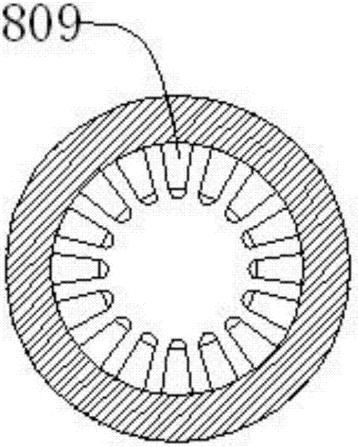
[0034] Such as figure 1 , figure 2 , image 3 , Figure 4As shown, a wax pneumatic extrusion device for soaking casting, including a base 1, a barrel 2, an upper cover 3, an air inlet pipe 4, a guide rod 5, a piston 6, a lifting cylinder 7, a heating mechanism 8, a discharge Tube 9, cooling jacket 10, controller 11, the barrel 2 is located at the upper end of the base 1, the barrel 2 is threadedly connected with the base 1, the upper cover 3 is located at the upper end of the barrel 2, and the upper The cover 3 is connected to the barrel 2 with gaps, the air intake pipe 4 is located at the upper end of the upper cover 3, the air intake pipe 4 is threadedly connected with the upper cover 3, the guide rod 5 runs through the upper cover 3, and the guide rod 5 is connected with the upper cover 3 with a gap, the piston 6 is located at the lower end of the guide rod 5 and inside the barrel 2, the piston 6 is threaded with the guide rod 5 and connected with the barrel 2 with a ga...
PUM
Abstract
The invention discloses a wax pneumatic extruding device for soaking type casting, which comprises a base, a barrel, an upper cover, an air inlet pipe, a guide rod, a piston, a lifting cylinder, a heating mechanism, a discharge pipe, a cooling jacket and a controller , the controller controls the lifting cylinder to push the upper cover up, pulls the piston out under the action of the limit block, and puts the solid wax material into the barrel; when extruding, the controller controls the heating mechanism to work on the material The wax in the barrel is heated, and then, compressed air is pumped into the barrel through the inlet pipe, thereby pushing the piston down to squeeze out the melted wax through the outlet pipe, and at the same time, pump compressed air into the cooling jacket through the inlet joint. Air, thereby cooling the discharge pipe, makes the liquid wax turn into molten wax. The structure of the device is simple, the wax is extruded uniformly and continuously, and at the same time, it is driven by gas, has good protection performance and low maintenance cost.
Description
technical field [0001] The invention relates to a mechanical device, in particular to a wax pneumatic extruding device for homogeneous casting. Background technique [0002] Wax mold precision casting, also known as lost wax casting or investment casting, the specific casting method is: first make a model of the casting to be made with wax material, and weld the model to the sprue rod with the same material to make Dip the module (when the casting is large, it can be a single group), dip the refractory paint (a mixture of water glass or silica sol and fine sand) on the surface of the module, and then sprinkle refractory sand, (dip and sand should be repeated several times , so that the sand layer is thick enough), after it is dry and solidified, heat the mold group, release the wax material from the gate, form an empty shell, roast the empty shell to make it a strong mold shell, and pour the metal liquid from the pouring It is poured into the mouth, and after condensation, ...
Claims
Application Information
Patent Timeline
Application Date:The date an application was filed.
Publication Date:The date a patent or application was officially published.
First Publication Date:The earliest publication date of a patent with the same application number.
Issue Date:Publication date of the patent grant document.
PCT Entry Date:The Entry date of PCT National Phase.
Estimated Expiry Date:The statutory expiry date of a patent right according to the Patent Law, and it is the longest term of protection that the patent right can achieve without the termination of the patent right due to other reasons(Term extension factor has been taken into account ).
Invalid Date:Actual expiry date is based on effective date or publication date of legal transaction data of invalid patent.