Stamping device and stamping method thereof

A punching device and punch technology, applied in the punching device and the punching field thereof, can solve the problems of increasing the manufacturing cost and high manufacturing cost of the punching device, and achieve the effect of improving the feeding stability.

Active Publication Date: 2017-06-16
METAL INDS RES & DEV CENT
View PDF5 Cites 2 Cited by
  • Summary
  • Abstract
  • Description
  • Claims
  • Application Information

AI Technical Summary

Problems solved by technology

[0004] However, the same stamping device can usually only produce processed products with exactly the same size. When the user wants to change the size of the processed product in a certain dimension (such as horizontal or vertical), it is necessary to use multiple punches with different specifications. stamping device, and in the process of preparing multiple stamping devices with different specifications, it is bound to increase the overall manufacturing cost of the stamping device
Therefore, when producing processed products of different sizes in a single dimension, the existing stamping device has the problem of high manufacturing cost
[0005] In view of this, a stamping device and its stamping method are provided to solve the problem of high manufacturing cost when the existing stamping device or method produces finished products with different sizes in a single dimension

Method used


Image

  • Stamping device and stamping method thereof
  • Stamping device and stamping method thereof
  • Stamping device and stamping method thereof

Examples


Embodiment Construction

[0046] In order to make the above and other purposes, features and advantages of the present invention more comprehensible, the preferred embodiments of the present invention are specifically cited below, together with the accompanying drawings, as follows:

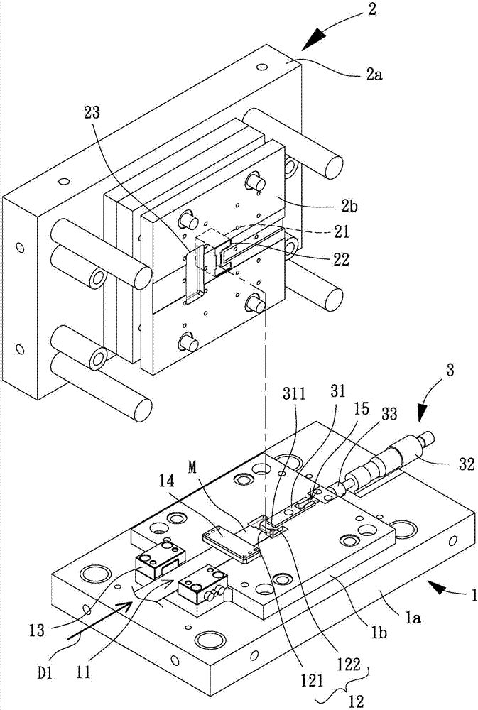
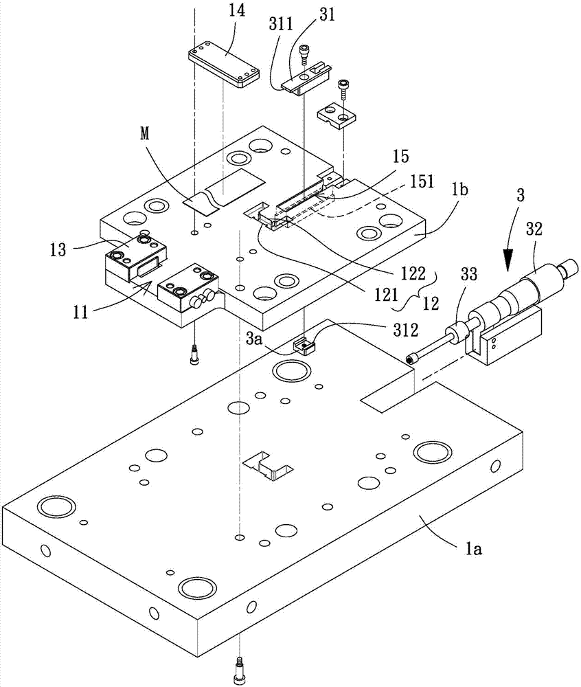
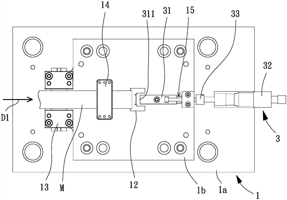
[0047] Please refer to figure 1 As shown, it is a three-dimensional exploded view of the stamping device of the present invention. The stamping device includes a first mold base 1, a second mold base 2 and a variable guide assembly 3. The second mold base 2 is correspondingly arranged on the first mold base. On one side of a mold base 1 , the variable guide assembly 3 is combined with the first mold base 1 .

[0048] The first mold base 1 has a feeding guide 11 and a die hole 12, the feeding guide 11 extends along a feeding direction D1, the feeding guide 11 can guide a material M along the feeding Moving in the direction D1 allows the material M to approach the die hole 12 smoothly, wherein the material M can be a metal...


PUM


Abstract

A stamping device and a stamping method thereof are disclosed. The stamping method is performed using the stamping device. The stamping device comprises a first die holder having a feeding guide groove extending along a feeding direction and a die orifice; a second die holder, provided on one side of the first die holder and having a punch corresponding to the die orifice; and a variable guide assembly having a positioning block which is slidably coupled to the first die holder along the feeding direction. By the structure, it is possible to produce a finished product having a different size in a single dimension, thereby reducing the manufacturing cost.

Description

technical field [0001] The present invention relates to a stamping device and a stamping method thereof, in particular to a stamping device and a stamping method which can be used to manufacture processed products with different sizes in a single dimension. Background technique [0002] Stamping is a widely used metal processing method. It mainly cuts, bends or compresses a metal material through a stamping device, and then processes the material into a finished product specified by the mold of the stamping device. shape and size. [0003] Generally speaking, the existing stamping device usually includes an upper die and a lower die, the upper die is provided with a punch for punching the material, the lower die is provided with a die hole corresponding to the punch, and the lower die is provided with a die hole corresponding to the punch. The mold can carry the material. When stamping is to be performed, the upper mold can be pressed against the lower mold, and the punch c...

Claims


Application Information

Patent Timeline
Patent Type & Authority Applications(China)
IPC IPC(8): B21D22/02
CPCB21D22/02
Inventor 蔡行知黄守成王心德廖振昇刘育达简柏轩黄建发
Owner METAL INDS RES & DEV CENT
Why Eureka
Try Eureka