Automatic feeding device of rod material automatic conveying machine

An automatic feeding and feeding technology, which is applied in the direction of conveyor objects, transportation and packaging, etc., can solve the problems of abnormal feeding, bar blockage, economic loss, etc., and achieves good feeding stability, reasonable design, and is not easy to separate Effect

Active Publication Date: 2015-03-25
盐城福万家保温板有限公司
View PDF5 Cites 1 Cited by
  • Summary
  • Abstract
  • Description
  • Claims
  • Application Information

AI Technical Summary

Problems solved by technology

Although the above solution can increase the feeding speed by using mechanical actions instead of manual labor, since the feeding mechanism cannot control the feeding speed of the rods, it is easy to cause the feeding mechanism to fail if the rods on the feeding mechanism have not left. The mechanism continues to transport the rods to the feeding mechanism due to failure to detect, resulting in the phenomenon that the rods on the feeding mechanism are blocked and cannot be fed normally, resulting in production accidents and economic losses to the enterprise

Method used


Image

  • Automatic feeding device of rod material automatic conveying machine

Examples


Embodiment 1

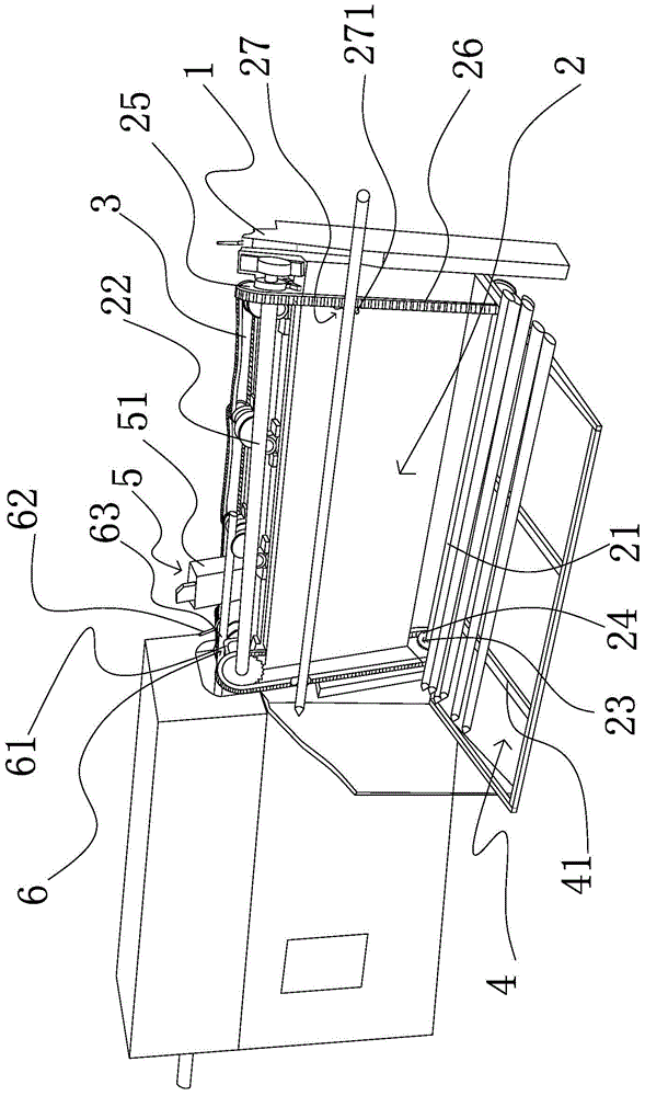
[0017] As shown in Figure 1, the automatic feeding device of this automatic bar feeding machine includes a material storage mechanism 4 arranged on one side of the frame 1 and below the feeding mechanism 3 on the frame 1, the described material storage mechanism 4 and the frame 1 are provided with a lifting mechanism 2 that can horizontally lift the bars placed in the storage mechanism 4 one by one and place the bars on the delivery mechanism 3 one by one. The lifting mechanism 2 is connected to the bar conveying detection mechanism 5 provided at the conveying mechanism 3 and the lifting mechanism 2 can act according to the signal collected by the bar conveying detection mechanism 5 .

[0018] More specifically, the material lifting mechanism 2 includes a driving shaft 21 and a driven shaft 22 that are parallel to each other and are horizontally arranged. A driver 23 is connected to the driving shaft 21 and the bar material delivery detection mechanism 5 is connected to the dri...

Embodiment 2

[0023] As shown in Figure 1, an automatic feeding device for a bar automatic feeding machine, its technical solution is basically the same as that of Embodiment 1, the only difference is that the driving wheel 24 and the driven wheel 25 are not only chains The wheel can also be a pulley or a sheave, and the endless transmission member 26 can be a belt or a rope.

Embodiment 3

[0025] As shown in Figure 1, an automatic feeding device for a bar automatic feeding machine, its technical scheme is basically the same as that of Embodiment 1, the only difference is that there are at least 6 lifting parts 27 arranged on each annular transmission part 26. Pairs and each pair is arranged in a one-to-one correspondence in the horizontal direction to increase the delivery capacity of the bar.


PUM


Abstract

The invention belongs to the technical field of mechanical material automatic conveying in machining and particularly relates to an automatic feeding device of the rod material automatic conveying machine. The automatic feeding device comprises a material storage mechanism which is arranged on one side of a machine frame and is placed below a material conveying mechanism on the machine frame. A material lifting mechanism which can lift rod materials placed in the material storage mechanism one by one horizontally and place the rod materials in the material conveying mechanism is arranged between the material storage mechanism and the machine frame. The material lifting mechanism is connected with a rod material conveying detecting mechanism arranged at the material conveying mechanism and can move according to signals collected by the rod material conveying detecting mechanism. Compared with the prior art, the automatic feeding device of the rod material automatic conveying machine has the advantages of being reasonable in design, simple in structure and good in feeding stability, the rod materials cannot be separated easily, the rod materials can be supplied according to needs, and the device and other equipment operate in a coordinating mode.

Description

technical field [0001] The invention belongs to the technical field of automatic conveying of mechanical materials in mechanical processing, and in particular relates to an automatic feeding device of a bar automatic feeding machine. Background technique [0002] Due to the continuous development and progress of machinery manufacturing and processing enterprises, as well as the continuous rise of labor costs, the feeding mode of manual handling of bars has been difficult to meet the actual needs. For this reason, people have carried out long-term exploration. For example, the Chinese patent whose authorized announcement number is CN201432070Y discloses a kind of automatic feeding mechanism for rods, which is characterized in that: it includes a bracket and at least two rings arranged on the bracket along the same inclination angle. The conveying chain is provided with a plurality of baffle plates with a certain interval, and the conveying chain is connected with a power devi...

Claims


Application Information

Patent Timeline
Patent Type & Authority Applications(China)
IPC IPC(8): B65G47/12
Inventor 阎盛成阎学议
Owner 盐城福万家保温板有限公司
Why Eureka
Try Eureka