Convex-and-concave probe and plasma diagnosis method thereof
A technology of plasma and concave probe, which is applied in the field of plasma, can solve the problems of inaccurate diagnosis results, etc., and achieve the effect of accurate electron energy distribution function, accurate calculation of electron density, and good quality of volt-ampere characteristic curve
- Summary
- Abstract
- Description
- Claims
- Application Information
AI Technical Summary
Problems solved by technology
Method used
Image
Examples
Embodiment 1
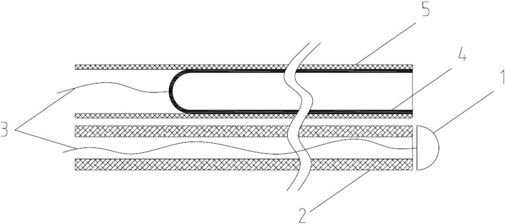
[0023] figure 1 The convex probe 1, the insulating tube 2 and the metal wire 3 form a convex probe assembly; the convex probe 1 is hemispherical and has a diameter of 2 mm; the insulating tube 2 has the same diameter as the convex probe 1; the plane part of the hemisphere of the convex probe 1 It is directly opposite to one end of the insulating tube 2, leaving a gap of 0.2mm in between; the convex probe 1 is connected to the metal wire 3 on the plane of the hemisphere, and the metal wire 3 passes through the insulating tube 2 to connect with the external circuit.
[0024] figure 1 Concave probe 4, insulating sleeve 5 and metal wire 3 form a concave probe assembly; concave probe 4 is cylindrical, with an inner diameter of 1.7mm and a depth of 30mm; one end of the cylinder of concave probe 4 is open, and the concave probe 4 cylinders are tightly sleeved with an insulating sleeve 5, and the edge of one end of the concave probe 4 cylinder is flush with the edge of the insulating...
Embodiment 2
[0028] figure 2 The convex probe 1, the insulating tube 2 and the metal wire 3 form a convex probe assembly; the convex probe 1 is hemispherical, with a diameter of 1.8 mm; the insulating tube 2 is the same diameter as the convex probe 1; the plane of the hemisphere of the convex probe 1 The part is facing one end of the insulating tube 2, leaving a gap of 0.16mm between them; the convex probe 1 is connected to the metal wire 3 on the plane of the hemisphere, and the metal wire 3 passes through the insulating tube 2 to connect with the external circuit.
[0029] figure 2 The concave probe 4, the insulating sleeve 5 and the metal wire 3 form a concave probe assembly; the concave probe 4 is cylindrical, with an inner diameter of 2 mm and a depth of 30 mm; one end of the concave probe 4 cylinder is open, and the concave probe 4 An insulating sleeve 5 is tightly sleeved on the outside of the cylinder, and the edge of the open end of the concave probe 4 cylinder is flush with th...
Embodiment 3
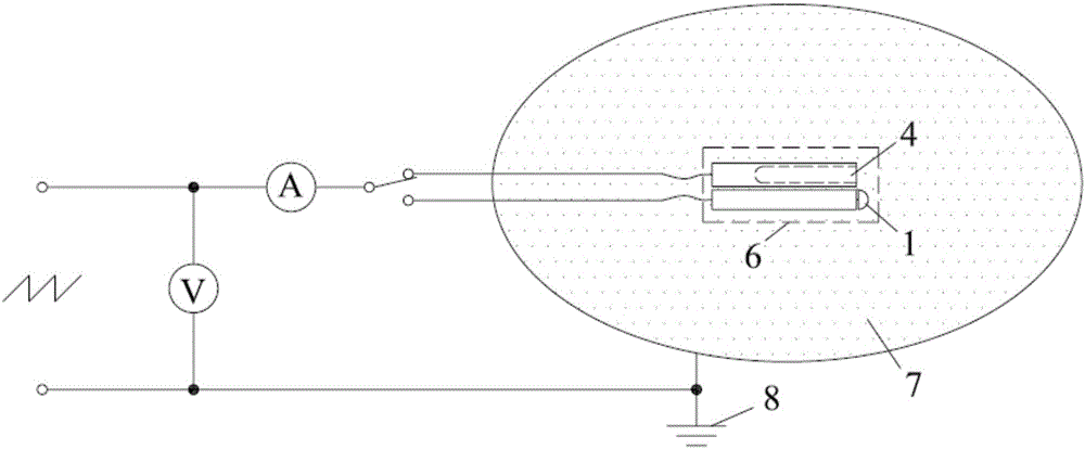
[0033] image 3 The convex probe assembly and the concave probe assembly constitute a split-type convex and concave probe assembly 6 placed in the plasma 7; at the same time, a scanning bias voltage is applied between the convex probe 1 and the concave probe 4 and the plasma ground electrode 8 , and measuring the variation of the respective currents of the convex probe 1 and the concave probe 4 with the scanning bias voltage, and obtaining the respective volt-ampere characteristic curves of the convex probe and the concave probe.
PUM
| Property | Measurement | Unit |
|---|---|---|
| The inside diameter of | aaaaa | aaaaa |
| Diameter | aaaaa | aaaaa |
| The inside diameter of | aaaaa | aaaaa |
Abstract
Description
Claims
Application Information
 - R&D
- Intellectual Property
- Life Sciences
- Materials
- Tech Scout
- Unparalleled Data Quality
- Higher Quality Content
- 60% Fewer Hallucinations
Browse by: Latest US Patents, China's latest patents, Technical Efficacy Thesaurus, Application Domain, Technology Topic, Popular Technical Reports.
© 2025 PatSnap. All rights reserved.Legal|Privacy policy|Modern Slavery Act Transparency Statement|Sitemap|About US| Contact US: help@patsnap.com


