
Video delay testing device in monitoring system

A delay test and monitoring system technology, applied in closed-circuit television systems, televisions, electrical components, etc., can solve the problems that the cameras cannot capture signals at both ends at the same time, and the video delay calculation cannot be applied, so as to achieve the effect of improving the technical level

Active Publication Date: 2017-06-13
SHANGHAI ADVANCED RES INST CHINESE ACADEMY OF SCI
View PDF10 Cites 20 Cited by
  • Summary
  • Abstract
  • Description
  • Claims
  • Application Information

AI Technical Summary

Problems solved by technology

In engineering applications, video encoders and decoding display units are often placed on both sides of a long physical distance, and it is impossible to use cameras to capture signals at both ends at the same time, so this invention patent cannot be applied to video delay calculations in engineering

Method used


Image

  • Video delay testing device in monitoring system
  • Video delay testing device in monitoring system
  • Video delay testing device in monitoring system

Examples


Embodiment Construction

[0031] Embodiments of the present invention are described below through specific examples, and those skilled in the art can easily understand other advantages and effects of the present invention from the content disclosed in this specification. The present invention can also be implemented or applied through other different specific implementation modes, and various modifications or changes can be made to the details in this specification based on different viewpoints and applications without departing from the spirit of the present invention.

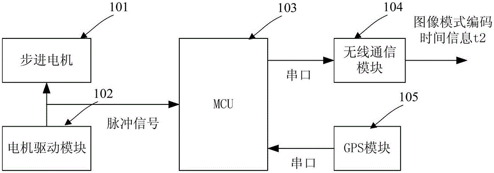
[0032] see Figure 1 ~ Figure 3 . It should be noted that the diagrams provided in this embodiment are only schematically illustrating the basic idea of ​​the present invention, so that only the components related to the present invention are shown in the diagrams rather than the number, shape and Dimensional drawing, the type, quantity and proportion of each component can be changed arbitrarily during actual implementation, and the ...


PUM


Abstract

The invention provides a video delay testing device in a monitoring system. The device comprises a video signal generator, a video delay analysis unit and a synchronization link, wherein the video signal generator is used for generating a continuously changing time varying video signal and a timestamp of each frame of image and packaging and transmitting image mode information and time information to the delay analysis unit; the video delay analysis unit is used for identifying a frame mode of a decoded video to determine system time generated by the frame mode and subtracting frame mode occurrence time from the system time which is decoded and displayed currently to obtain video transmission delay of the system; and the synchronization link is used for realizing synchronization of the video signal generator and the video delay analysis unit. The device solves a problem of video delay measurement in an actual engineering application, provides the realizable video delay measurement device and method for related professional institutes and construction units, fills a blank of the measurement field and improves the technological level of the national security and protection system, especially the monitoring system.

Description

technical field [0001] The present invention relates to a video delay measurement device, in particular to a video delay test device in a monitoring system, which can measure the video delay of a multimedia system with the camera part as image input, and the device can be used in a laboratory environment It realizes the measurement of the video delay performance of the multimedia system, and can also be used on the engineering site to realize the measurement of the video delay performance of the multimedia system under a large physical span. Background technique [0002] Video delay is an important technical indicator of multimedia system. In end-to-end applications, video delay includes three parts: encoding delay of video encoder, transmission delay and decoding display delay. For example, in video access control equipment, video delay will affect the user's subjective experience; in closed-loop In a video surveillance system, delay determines the timeliness of video info...

Claims


Application Information

Patent Timeline
Patent Type & Authority Applications(China)
IPC IPC(8): H04N17/00H04N7/18
CPCH04N7/18H04N17/00
Inventor 刘立庄赵丹张浩
Owner SHANGHAI ADVANCED RES INST CHINESE ACADEMY OF SCI
Learn More