
A kind of preparation method of composite cathode material of graphene/zinc oxide/graphene sandwich structure for field emission

A technology of ene sandwich and composite cathode, which is applied in nanotechnology for materials and surface science, cold cathode manufacturing, discharge tube/lamp manufacturing, etc., can solve the problem of stability and controllability of directional ZnO nanoneedle arrays Mature, insufficient understanding of the law of influence, field enhancement factor reduction, etc., to achieve the effect of low launch field strength, low cost, and low launch performance

Active Publication Date: 2019-01-08
深圳前海石墨烯产业有限公司
View PDF11 Cites 0 Cited by
  • Summary
  • Abstract
  • Description
  • Claims
  • Application Information

AI Technical Summary

Problems solved by technology

Recent studies have shown that the needle-like nano-ZnO emitter has the smallest turn-on field strength and threshold field strength, and its directional arrangement has better field emission performance than the disordered structure. Within a certain range, the greater the array density, the greater the emission current , but if the density exceeds a certain range, the shielding effect between the needles will cause the field enhancement factor to decrease
However, up to now, the preparation process of oriented ZnO nanoneedle arrays is still immature in terms of stability and controllability, and the understanding of the influence law between array density and field emission enhancement factor is not sufficient.

Method used


Image

  • A kind of preparation method of composite cathode material of graphene/zinc oxide/graphene sandwich structure for field emission
  • A kind of preparation method of composite cathode material of graphene/zinc oxide/graphene sandwich structure for field emission
  • A kind of preparation method of composite cathode material of graphene/zinc oxide/graphene sandwich structure for field emission

Examples


Embodiment 1

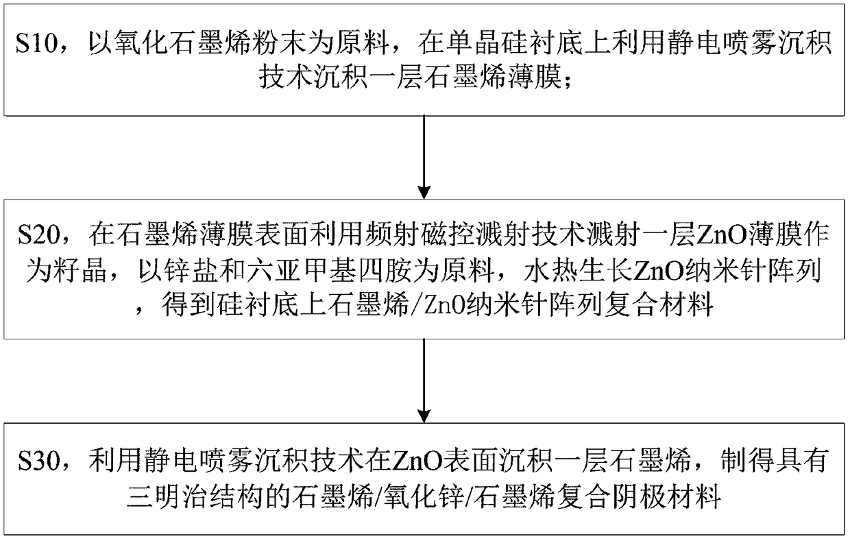
[0038] like figure 1As shown, measure 33.33ml of analytically pure 1,2-propanediol with a mass percentage of 99.5% and 66.67ml of analytically pure ethanol with a mass percentage of 99.8%, and mix the two fully to obtain 1,2-propanediol and 100ml of a mixed solution with an absolute ethanol volume ratio of 1:2, 0.05mmol mass percentage of 99% analytically pure graphene oxide powder was dissolved in the mixed solution, and after ultrasonic stirring for 1h, an electrostatic spray deposition (ESD) was obtained. Suspend the precursor solution; then fix the N-type monocrystalline silicon polished wafer (resistivity 3) on the substrate splint, heat the substrate temperature to 100°C, and adjust the capillary nozzle of the electrostatic spray deposition device and the substrate The distance between them is 5cm, and the DC voltage is 12kV. Add the prepared electrostatic spray deposition precursor solution to the electrostatic spray deposition device, set the liquid flow rate of the e...

Embodiment 2

[0041] like figure 1 As shown, measure 50ml of analytically pure 1,2-propanediol with a mass percentage of 99.5% and 50ml of analytically pure absolute ethanol with a mass percentage of 99.8%, and mix the two thoroughly to obtain 1,2-propanediol and anhydrous The volume ratio of ethanol is 100ml of mixed solution of 1:1, and 0.03mmol mass percent of 99% analytically pure graphene oxide powder is dissolved in the mixed solution, and after ultrasonic stirring for 1.5h, an electrostatic spray deposition (electrostatic spray deposition) is obtained. Then fix the N-type monocrystalline silicon polished wafer (resistivity 8.1) on the substrate splint, heat the substrate temperature to 150°C, adjust the capillary nozzle and lining of the electrostatic spray deposition device The distance between the bottoms is 6cm, and the DC voltage is 11kV. Add the prepared electrostatic spray deposition precursor solution to the electrostatic spray deposition device, set the spray speed of the el...

Embodiment 3

[0044] like figure 1 As shown, measure 33.33ml of analytically pure 1,2-propanediol with a mass percentage of 99.5% and 66.67ml of analytically pure ethanol with a mass percentage of 99.8%, and mix the two fully to obtain 1,2-propanediol and 100ml of a mixed solution with a volume ratio of absolute ethanol of 1:2, 0.02 mmol of analytically pure graphene oxide powder with a mass percentage of 99% was dissolved in the mixed solution, and after ultrasonic stirring for 1 hour, electrostatic spray deposition (electrostatic spray deposition) was obtained. The suspension precursor solution used; then fix the N-type monocrystalline silicon polished wafer (resistivity 5.8) on the substrate splint, heat the substrate temperature to 200 ° C, adjust the capillary nozzle and the electrostatic spray deposition device The distance between the substrates is 6cm, and the DC voltage is 10kV. Add the prepared electrostatic spray deposition precursor solution to the electrostatic spray depositio...


PUM

PropertyMeasurementUnit
thicknessaaaaaaaaaa

Abstract

The present invention belongs to the vacuum microelectronics and display technology field, and especially relates to a preparation method for grapheme / zinc oxide / grapheme sandwich structure composite cathode materials for field emission. The method comprises the following steps: S10, taking graphene oxide powder as raw materials, employing an electrostatic spraying deposition technology to deposit a layer of grapheme film on a monocrystalline silicon substrate; S20, employing a radio-frequency magnetron sputtering technology to sputter a layer of ZnO film as seed crystal at the surface of the grapheme film, taking zinc salt and hexamine as raw materials, performing hydrothermal growth of a ZnO nanoneedle array, and obtaining grapheme / ZnO nanoneedle array composite materials on the silicon substrate; and S30, employing the electrostatic spraying deposition technology to deposit a layer of grapheme at the ZnO surface, and making grapheme / zinc oxide / grapheme composite cathode materials with a sandwich structure. The preparation technology is high in operationality, is not high in device requirement and low in cost, can perform large-scale rapid preparation, and is helpful to be compatible with the large-scale production technology, and therefore the obtained grapheme / zinc oxide / grapheme sandwich structure composite cathode materials are low in field emission opening field intensity and stable in emission performance.

Description

technical field [0001] The invention belongs to the field of vacuum microelectronics and display technology, and in particular relates to a method for preparing a composite cathode material with a graphene / zinc oxide / graphene sandwich structure for field emission. Background technique [0002] In today's rapidly developing information age, in order to improve the "portability" of electronic equipment and realize the flat and miniaturization of display components, the development of cold cathode field emission technology has obvious advantages over traditional hot cathode ray tube display technology. The cold cathode field emission display uses the electron beam emitted by the cold cathode to hit the fluorescent screen to cause light to display images. It avoids the preheating system while maintaining excellent image quality. It has low turn-on field strength, low power consumption, small size, and super structure. Thinning and other characteristics. [0003] The core techno...

Claims


Application Information

Patent Timeline
Patent Type & Authority Patents(China)
IPC IPC(8): H01J9/02B82Y30/00B82Y40/00
CPCB82Y30/00B82Y40/00H01J9/025
Inventor 杨璞武军张庆泽郑昌垒宋开新徐军明
Owner 深圳前海石墨烯产业有限公司
Learn More