
Intelligent relay protection testing instrument with good display effect and capable of automatically adjusting angle

A technology for automatic adjustment and display effect, applied in the field of electric meters, which can solve the problems of easy wear and tear on the screen surface, unreliable supporting equipment, and easy adsorption of dust and impurities on the screen surface, so as to achieve convenient observation and operation, good display effect, and display effect. good effect

Inactive Publication Date: 2017-06-13
SHENZHEN ANSIKE ELECTRONICS TECH CO LTD
View PDF6 Cites 5 Cited by
  • Summary
  • Abstract
  • Description
  • Claims
  • Application Information

AI Technical Summary

Problems solved by technology

[0003] The display screen on the existing relay protection tester is usually directly exposed to the outside of the device, which causes the surface of the screen to easily absorb dust and impurities, and also makes the surface of the screen easy to wear and tear, which in turn affects the display effect of the device. Not only that, the existing In order to face the display screen directly to the staff, the relay protection tester usually uses the turning handle and uses the handle as a supporting foot to tilt the device. However, this display method is likely to cause the handle support device to be unstable due to the loosening of the handle. At the same time, because the structure of the handle is fixed and single, the inclination angle of the equipment is fixed. In the process of use, the observation position of the staff usually changes. less practical

Method used


Image

  • Intelligent relay protection testing instrument with good display effect and capable of automatically adjusting angle
  • Intelligent relay protection testing instrument with good display effect and capable of automatically adjusting angle
  • Intelligent relay protection testing instrument with good display effect and capable of automatically adjusting angle

Examples


Embodiment Construction

[0028] The present invention is described in further detail now in conjunction with accompanying drawing. These drawings are all simplified schematic diagrams, which only illustrate the basic structure of the present invention in a schematic manner, so they only show the configurations related to the present invention.

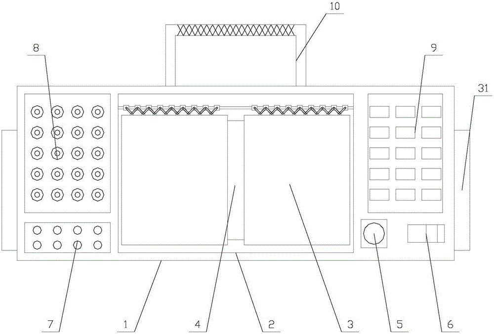
[0029] Such as Figure 1-Figure 5 As shown, an intelligent relay protection tester with good display effect and automatic angle adjustment includes a main body 1 and support units 31 arranged on both sides of the main body 1, the main body 1 is provided with a notch 2, a switch 6 , a number of indicator lights 7, a number of signal line interfaces 8 and a number of control buttons 9, a display screen 4 and a dust-proof mechanism 3 are arranged in the recess 2;

[0030] The supporting unit 31 includes a moving unit, a first fixed block 13, a rotating rod 14, a sleeve 15 and a roller 16. A fixed block 13 is fixed on the main body 1, one end of the rotating rod...


PUM


Abstract

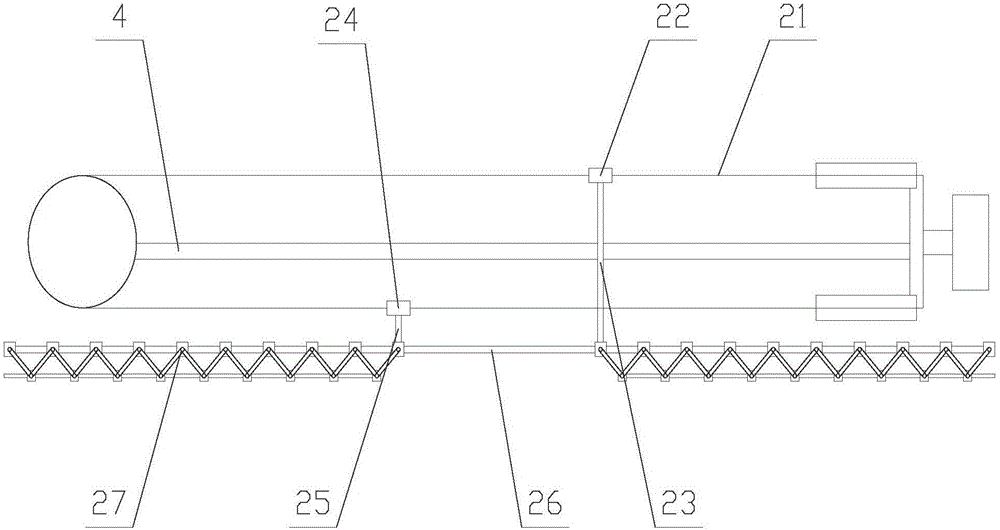
The invention relates to an intelligent relay protection testing instrument with good display effect and capable of automatically adjusting an angle. The intelligent relay protection testing instrument comprises a main body and supporting units which are arranged at the two sides of the main body, each supporting unit comprises a mobile unit, a first fixed block, a rotary rod, a sleeve and a roller, a dustproof mechanism comprises a driving unit, a fixing rod and two telescopic units, each telescopic unit comprises a second fixed block, a second connecting rod, a dustproof cloth and a plurality of telescopic components, and each telescopic component comprises a sliding block, a hinge block and two first connecting rods. The intelligent relay protection testing instrument with good display effect and capable of automatically adjusting the angle has the advantages that distance between the hinge blocks in the two telescopic units is increased by virtue of the dustproof mechanism, the dustproof cloth is unfolded to protect a display screen, and external destroy is avoided, so that equipment has a good display effect; besides, an angle of the main body is adjusted by virtue of the supporting units, so that the display screen is dead against a worker, the worker can carry out visual observation and operation conveniently, and practicability of the equipment is improved.

Description

technical field [0001] The invention relates to the field of electric meters, in particular to an intelligent relay protection tester with good display effect and automatic angle adjustment. Background technique [0002] The relay test protection instrument is based on the "Technical Conditions for Microcomputer Relay Protection Test Device (Discussion Draft)" issued by the Ministry of Electric Power, extensively listens to user opinions, summarizes the advantages and disadvantages of similar domestic products, and fully uses modern and advanced A new miniaturized microcomputer relay test protection realized by microelectronic technology and devices. When the power components in the power system (such as generators, lines, etc.) or the power system itself fail to endanger the safe operation of the power system, it can send a warning signal to the operator on duty in time, or directly send a trip command to the controlled circuit breaker To terminate the development of these...

Claims


Application Information

Patent Timeline
IPC IPC(8): G01R1/04
CPCG01R1/04
Inventor 曹燕红
Owner SHENZHEN ANSIKE ELECTRONICS TECH CO LTD
Learn More