Magnetic force flexible pivot

A flexible pivot and magnetic force technology, applied in the field of flexible pivot design, can solve problems such as fatigue and plastic deformation of mechanical spring leaf connection support, and achieve the effect of simple structure, ensuring concentricity, and easy manufacturing

Inactive Publication Date: 2017-06-13
BEIJING INST OF AEROSPACE TESTING TECH
View PDF5 Cites 2 Cited by
  • Summary
  • Abstract
  • Description
  • Claims
  • Application Information

AI Technical Summary

Problems solved by technology

[0003] The purpose of the present invention is to provide a magnetically flexible pivot, which uses magnetic force to realize non-contact support between the rotor and the stator, the air gap between the magnets ensures that the rotor rotates without friction, and the stable magnetic force provides highly repeatable rotation resistance. Overcome the inherent defects of mechanical spring leaf connection support fatigue, plastic deformation, etc.

Method used


Image

  • Magnetic force flexible pivot
  • Magnetic force flexible pivot
  • Magnetic force flexible pivot

Examples


Embodiment 1

[0029] Embodiment 1: Electromagnetic Magnetic Flexible Pivot

[0030] as attached figure 1 , attached figure 2 As shown, Embodiment 1 of the present invention provides an electromagnetic flexible magnetic pivot, including two parts: a rotor and a stator;

[0031] Further, the rotor includes an upper cover, a lower cover and a permanent magnet shaft, and the connection relationship is as follows: the upper cover and the lower cover are kept parallel and concentric with the permanent magnet shaft, and the upper cover, the lower cover and the permanent magnet shaft are fixed by rotor fixing screws 7 is fixed with the rotor nut 16, and the gasket 15 with anti-loosening ability is used for anti-loosening;

[0032] Further, the upper cover includes the rotor upper cover 5 and the upper cover thrust permanent magnet 1, and its connection relationship is: the upper cover thrust permanent magnet 1 is bonded and fixed in the groove of the rotor upper cover 5, and the upper cover thru...

Embodiment 2

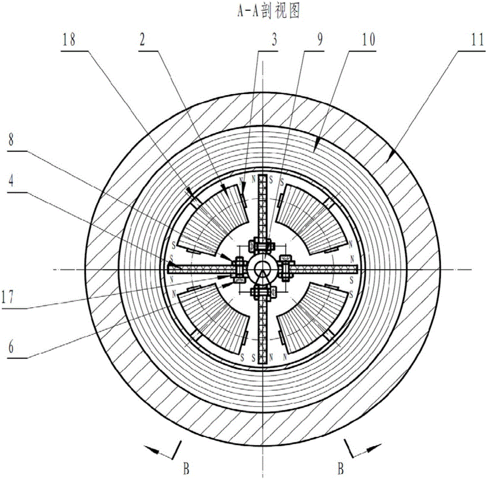
[0041] Embodiment 2: Permanent Magnetic Flexible Pivot

[0042] as attached image 3 , attached Figure 4 As shown, Embodiment 2 of the present invention provides a permanent magnetic flexible pivot. The difference from Embodiment 1 is that the stator thrust magnet and the stator anti-rotation magnet of the permanent magnet magnetic flexible pivot are permanent Magnet form, as follows:

[0043] The stator of the permanent magnetic flexible pivot includes a stator housing 11, an upper thrust permanent magnet 20, a lower thrust permanent magnet 21, and an anti-rotation permanent magnet 19; the connection relationship is: the upper thrust permanent magnet 20 is bonded fixed in the upper groove of the stator housing 11, and installed in parallel with the upper cover thrust permanent magnet 1, coaxial and magnetically mutually exclusive; the lower thrust permanent magnet 21 is bonded and fixed in the lower groove of the stator housing 11, Parallel and coaxial with the thrust per...

Embodiment 3

[0046] Example 3: Composite Magnetic Flexible Pivot

[0047] Embodiment 3 of the present invention provides a composite magnetic flexible pivot. The difference from Embodiment 1 and Embodiment 2 is that the stator thrust magnet and stator anti-rotation magnet of the magnetic flexible pivot are permanent magnets and electromagnetic coils. Mixed use.


PUM


Abstract

The invention discloses a magnetic force flexible pivot which comprises two parts including a stator and a rotor. A magnetic force manner is adopted for determining that the rotor has no friction rotation; the stator is provided with a blade type anti-rotation permanent magnet, and magnetic force between the blade type anti-rotation permanent magnet and an anti-rotation magnet of the rotor provides high-repeatability rotation resistance; the stator is provided with a thrust magnet, a thrust bearing manner is formed by the thrust magnet and a thrust permanent magnet of the rotor, and friction-free axial bearing force is provided; and the thrust magnet and the anti-rotation magnet on the stator have three achievement manners including permanent magnet, electromagnetism and compounding, and three manners including the permanent magnet magnetic force flexible pivot, the electromagnetic magnetic force flexible pivot and the compounding magnetic force flexible pivot are formed. The flexible pivot has the beneficial effects that friction is avoided, lubrication is avoided, the action face is large; the high-repeatability rotation resistance is provided, the limitation of the using time number of an existing cross-shaped spring type flexible pivot is eliminated, the extremity of the service life is avoided, the axial bearing force and the rotation resistance are controllable and adjustable, and flexibility and reliability are achieved.

Description

technical field [0001] The invention relates to the field of flexible pivot design, in particular to a magnetic flexible pivot. Background technique [0002] In the field of precision positioning and high-precision mechanical measurement, frictionless slewing bearings are required, while providing high repeatability of rotation resistance. Flexible pivots are the usual approach. Existing flexible pivots are also called cross springs, torsion pivots, or flex pivots in different occasions. This kind of flexible pivot is based on the principle of criss-cross spring leaf, which realizes rigid support for the axial direction and a certain degree of flexibility for rotation, and has the advantages of no gap, no friction and no lubrication. However, in the case of multiple reciprocating rotations of the spring leaf structure, fatigue fracture will occur due to alternating cyclic stress, which limits the service life. In particular, when the existing flexible pivot is used beyond...

Claims


Application Information

Patent Timeline
Patent Type & Authority Applications(China)
IPC IPC(8): F16C11/04
CPCF16C11/04
Inventor 周磊孙树江李斌朱子环陈锋蔡睿刘岳鹏马鑫刘万龙马军强
Owner BEIJING INST OF AEROSPACE TESTING TECH
Why Eureka
Try Eureka