Glass fiber cement non-removal formwork system, connection structure and construction method of connection structure
A technology without dismantling formwork and glass fiber, applied in the direction of building structure, building components, walls, etc., can solve the problems of occupying construction time, unfavorable number of pull bolts, large labor force, etc., to avoid design and overlapping, installation And the effect of simple and time-saving disassembly and reduction of the use of pull bolts
- Summary
- Abstract
- Description
- Claims
- Application Information
AI Technical Summary
Problems solved by technology
Method used
Image
Examples
Embodiment 1
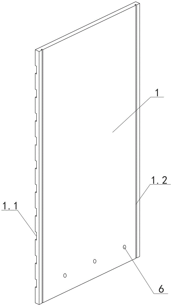
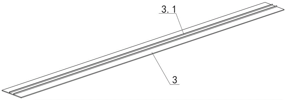
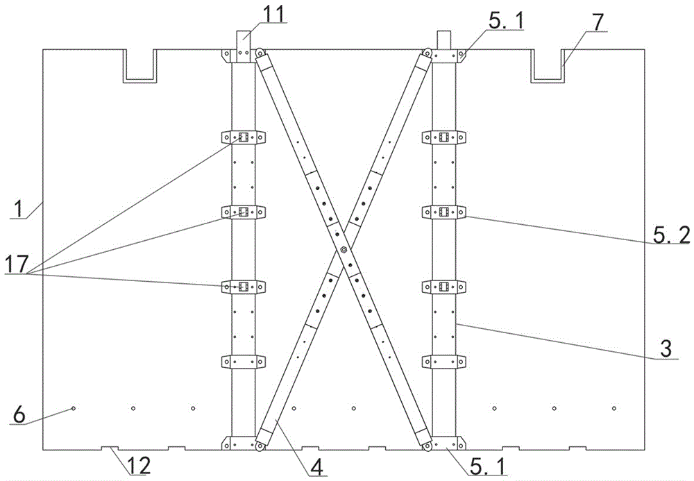
[0074] Embodiment one sees Figure 1-3 , Figure 6-10 , Figure 15-19 As shown, a glass fiber cement non-demolition formwork system includes a group of panel groups spliced by panel units 1 , a supporting frame structure at the back of the panel group and tension bolts 2 .
[0075] The panel unit 1 is a glass fiber reinforced cement board. In this embodiment, the size is length × width × thickness = 1200mm × 2400mm × 30mm. The inner surface of the panel unit 1 is provided with transverse interlocking reinforcing grooves 1.1 arranged at intervals. The size of the reinforced groove cross section is length×width=60mm×8mm, which is used to increase the bite force between the glass fiber cement board and the poured concrete. A vertical connection rib groove 1.2 is respectively provided on the outer surface of the panel unit at a distance of 30mm from the vertical edge, and the vertical connection rib groove 1.2 is arranged along the height direction of the panel unit.
[0076]...
Embodiment 2
[0089] Embodiment two see Figure 1-2 , Figure 4 , Figure 6-12 , Figure 15-19 As shown, different from the first embodiment, the cross-board connection assembly further includes at least one additional one-way cross-board fastener 8 between adjacent one-way cross-board connectors 5 . The one-way cross-slab fasteners are longitudinally arranged at intervals with the one-way cross-slab connectors, which play a role in connecting the frame steel strip and the panel unit.
[0090] The one-way cross-board fastener 8 is a "several"-shaped steel plate, including a second one-way main board 8a and two second one-way wing plates 8b symmetrically fixed on the inner two ends of the second one-way main board 9a, The distance between the two second one-way flaps 8 b is adapted to the width of the frame steel strip 3 , and the thickness of the second one-way flaps 8 b is the same as that of the frame steel strip 3 .
[0091] The second one-way main board 8a is provided with a second ...
Embodiment 3
[0092] Embodiment three see Figure 1-2 , Figure 5 , Figure 6-19 As shown, the difference from Example 2 is that although the formwork without dismantling is generally based on large sizes, if special parts or special process requirements are encountered and two or more layers of formwork are required to be spliced vertically, the panel The unit may include sub-unit boards 1a spliced up and down, and the direct horizontal joints of the sub-unit boards 1a may be bound with galvanized iron wires arranged at intervals of less than 100mm.
[0093] A two-way cross-board connector 9 is also added at the splicing position of the sub-unit board 1a. The two-way cross-board connector 9 is a "several"-shaped steel plate, including a two-way main board 12a and symmetrically fixed on both ends of the two-way main board 9a. Two two-way wing plates 9b, the two-way main board 9a has a two-way main board connection hole 9c and is fastened to the outer surface of the frame steel belt 3 ...
PUM
 Abstract
Description
Claims
Application Information
 - R&D
- Intellectual Property
- Life Sciences
- Materials
- Tech Scout
- Unparalleled Data Quality
- Higher Quality Content
- 60% Fewer Hallucinations
Browse by: Latest US Patents, China's latest patents, Technical Efficacy Thesaurus, Application Domain, Technology Topic, Popular Technical Reports.
© 2025 PatSnap. All rights reserved.Legal|Privacy policy|Modern Slavery Act Transparency Statement|Sitemap|About US| Contact US: help@patsnap.com


