
Buried charging device and charging method

A charging device and charging method technology, applied in charging stations, electric vehicle charging technology, electric vehicles, etc., can solve the problems of exposed lines, restrict the rapid development of charging piles, and fail to control multi-channel real-time communication, and achieve the effect of saving costs

Active Publication Date: 2017-06-13
ZHEJIANG XUEBOLAN TECH CO LTD
View PDF7 Cites 12 Cited by
  • Summary
  • Abstract
  • Description
  • Claims
  • Application Information

AI Technical Summary

Problems solved by technology

[0003] With the rapid development of electric vehicles, how to charge electric vehicles safely, quickly and efficiently has become a bottleneck restricting the development of electric vehicles. At present, there are charging piles fixed on the ground or walls or charging piles relying on the original street light poles. Or charging piles with wireless power supply. Although these measures have certain advantages at present, there are also many disadvantages. Although the charging piles with wireless power supply simplify the steps of plugging and unplugging the charging plug, the existing technology has no advantages in wireless power supply. There are still some shortcomings in terms of high-efficiency conversion and high power. In addition, the high cost and the inability to multi-channel real-time communication control are also problems to be solved. Although charging piles fixed on the ground or walls do not have such problems as wireless power supply, However, in cities where every inch of land is expensive, limited places make it impossible to build a large number of them, and a large number of lines are exposed, which also poses certain safety hazards, which also restricts the rapid development of this type of charging pile.

Method used


Image

  • Buried charging device and charging method
  • Buried charging device and charging method
  • Buried charging device and charging method

Examples


Embodiment Construction

[0022] In the following, the present invention will be described in detail through specific embodiments, so as to better understand the technology of the present invention.

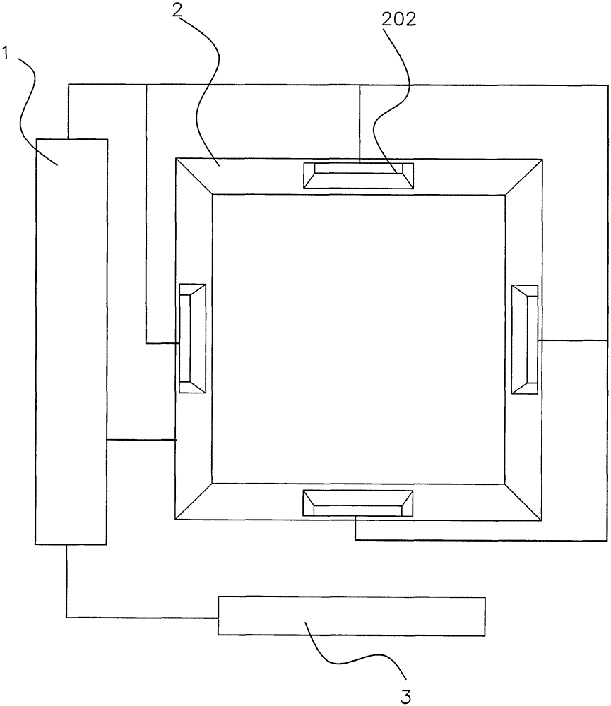
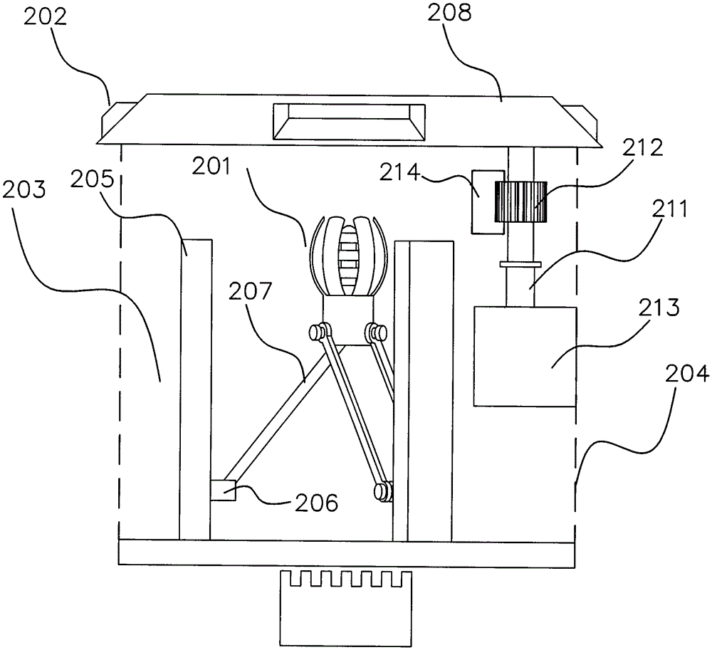
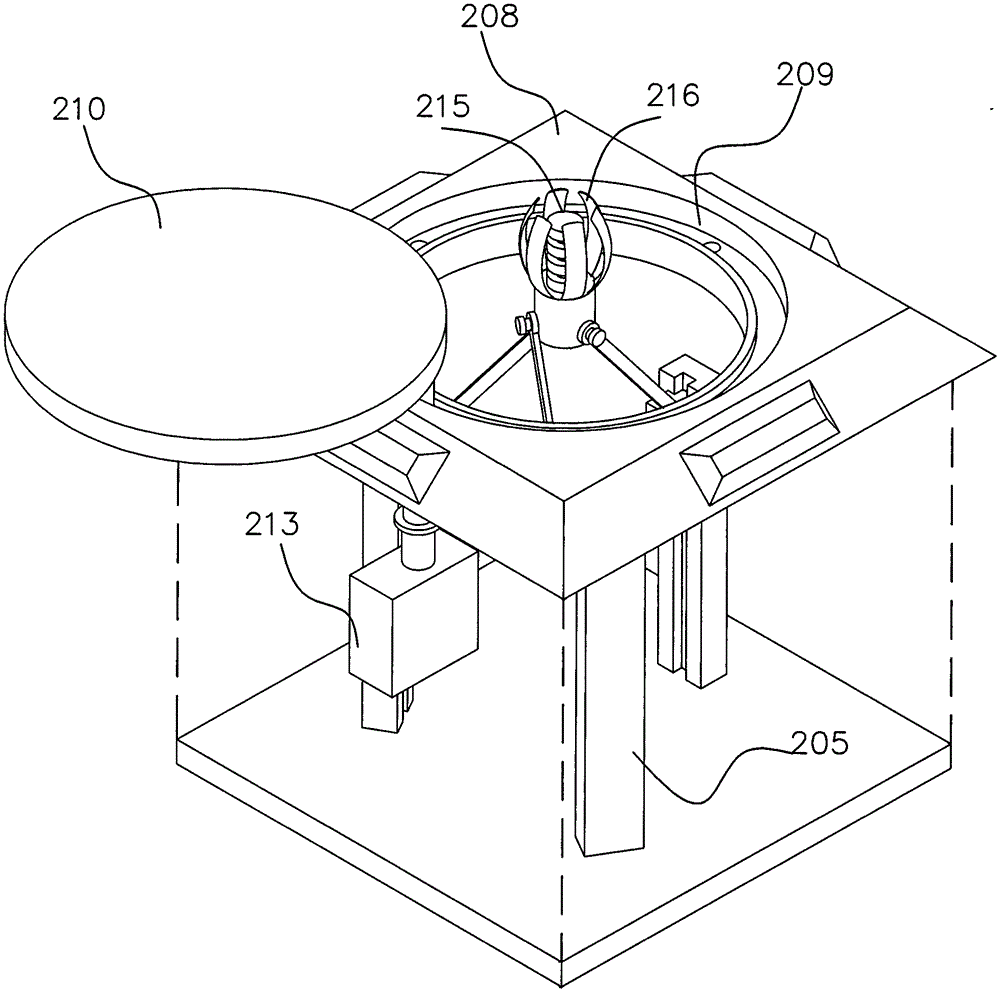
[0023] Such as Figure 1 to Figure 5 As shown; a buried charging device, including a control host 1, a buried charging pile 2 connected to the control host 1, a charging plug 201 arranged on the buried charging pile 3, and the There are several sensors 202 on the buried charging pile 2, the sensors 202 are connected to the control host 1, the sign 3 connected to the control host 1, and the charging on the buried charging pile 2 The plug 201 is connected with the lifting device 203 .

[0024] The buried charging pile 2 includes a buried installation box 204, the bottom of the buried installation box 204 is provided with several lifting columns 205, and the lifting columns 205 are provided with lifting heads 206, The lifting head 206 is provided with a rocker arm 207 , and the rocker arm 207 is movably co...


PUM


Abstract

The invention belongs to the field of new energy vehicles and in particular relates to a buried charging device and a charging method in the field. The buried charging device comprises a control host, a buried charging pile and a charging plug, wherein the buried charging pile is connected with the control host, and the charging plug is arranged on the buried charging pile; the buried charging device is characterized in that a plurality of sensors are arranged on the buried charging pile; the sensors are connected with the control host; a sign connected with the control host is arranged; and the charging plug on the buried charging pile is connected with a lifting device. The buried charging device can achieve that one host controls the plurality of buried charging piles; and as charging port automatic connection is adopted and the buried charging pile does not occupy any ground road, defects of the various traditional charging piles are effectively avoided, the bottleneck restricting the development of the electric vehicles is solved and the charging pile can be rapidly developed.

Description

technical field [0001] The invention belongs to the field of new energy vehicles, and in particular relates to a buried charging device and a charging method in the field. [0002] technical background [0003] With the rapid development of electric vehicles, how to charge electric vehicles safely, quickly and efficiently has become a bottleneck restricting the development of electric vehicles. At present, there are charging piles fixed on the ground or walls or charging piles relying on the original street light poles. Or charging piles with wireless power supply. Although these measures have certain advantages at present, there are also many disadvantages. Although the charging piles with wireless power supply simplify the steps of plugging and unplugging the charging plug, the existing technology has no advantages in wireless power supply. There are still some shortcomings in terms of high-efficiency conversion and high power. In addition, the high cost and the inability t...

Claims


Application Information

Patent Timeline
IPC IPC(8): B60L11/18
CPCB60L53/16B60L53/31B60L53/36Y04S30/12Y02T90/167Y02T10/70Y02T90/12Y02T10/7072Y02T90/14
Inventor 谭代英鲍旭辉杨小静
Owner ZHEJIANG XUEBOLAN TECH CO LTD
Learn More