Eureka AIR delivers breakthrough ideas for toughest innovation challenges, trusted by R&D personnel around the world.

Circuit board gong cutting process without pins on the workbench, CNC gong machine

A processing technology and circuit board technology, applied in metal processing machinery parts, metal processing equipment, manufacturing tools, etc., can solve the problems of difficult positioning, cumbersome positioning and installation procedures, etc., to simplify cumbersome procedures, simplify positioning operation procedures, positioning and installation. Process fast effect

Active Publication Date: 2019-05-17
雪龙数控设备(深圳)有限公司
View PDF6 Cites 0 Cited by
  • Summary
  • Abstract
  • Description
  • Claims
  • Application Information

AI Technical Summary

Problems solved by technology

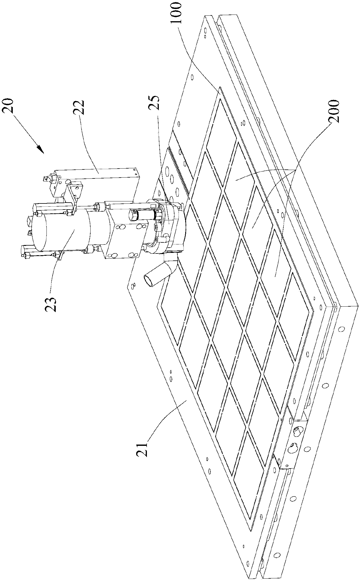
[0005] The purpose of the present invention is to provide a circuit board cutting process and a numerically controlled cutting machine that do not require pins on the workbench, aiming to solve the problem of cumbersome positioning and installation procedures and difficult positioning in the circuit board cutting process in the prior art

Method used


Image

  • Circuit board gong cutting process without pins on the workbench, CNC gong machine
  • Circuit board gong cutting process without pins on the workbench, CNC gong machine
  • Circuit board gong cutting process without pins on the workbench, CNC gong machine

Examples


Embodiment Construction

[0031] In order to make the object, technical solution and advantages of the present invention clearer, the present invention will be further described in detail below in conjunction with the accompanying drawings and embodiments. It should be understood that the specific embodiments described here are only used to explain the present invention, not to limit the present invention.

[0032] It should be noted that when an element is referred to as being “fixed” or “disposed on” another element, it may be directly on the other element or be indirectly on the other element. When an element is referred to as being "connected to" another element, it can be directly connected to the other element or indirectly connected to the other element.

[0033] It should also be noted that the orientation terms such as left, right, up, and down in this embodiment are only relative concepts or refer to the normal use state of the product, and should not be regarded as limiting.

[0034] See ...


PUM


Abstract

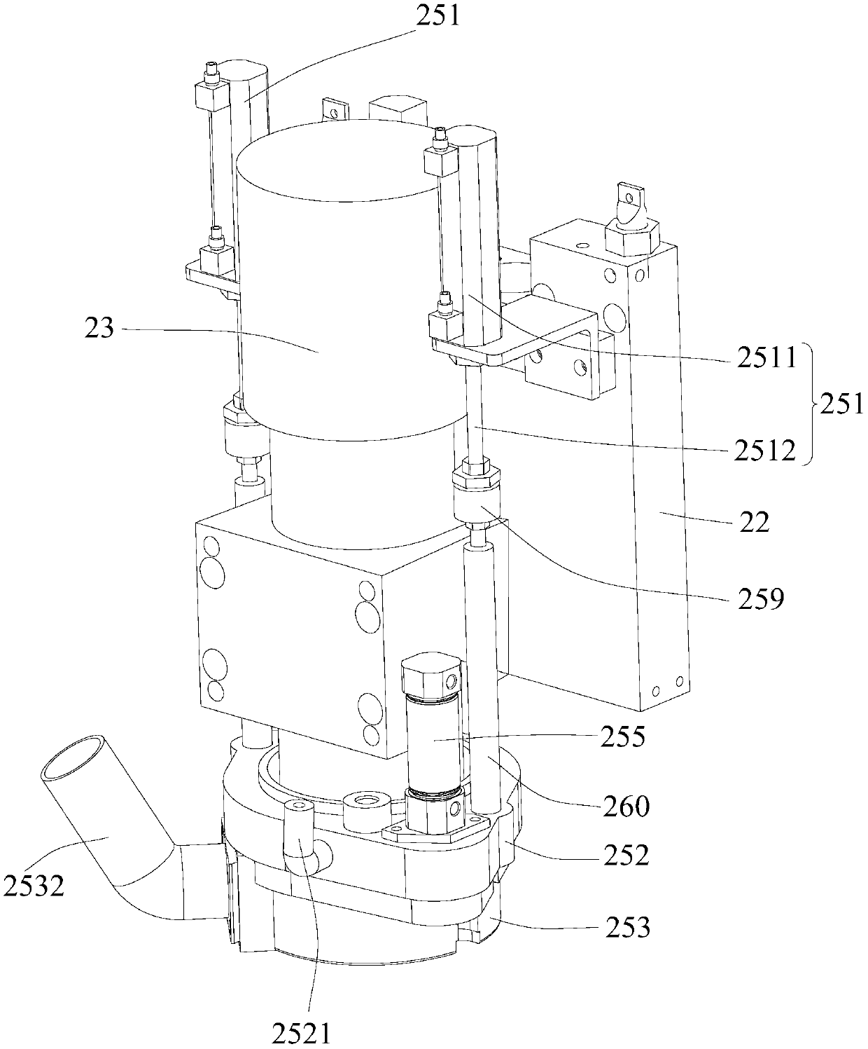
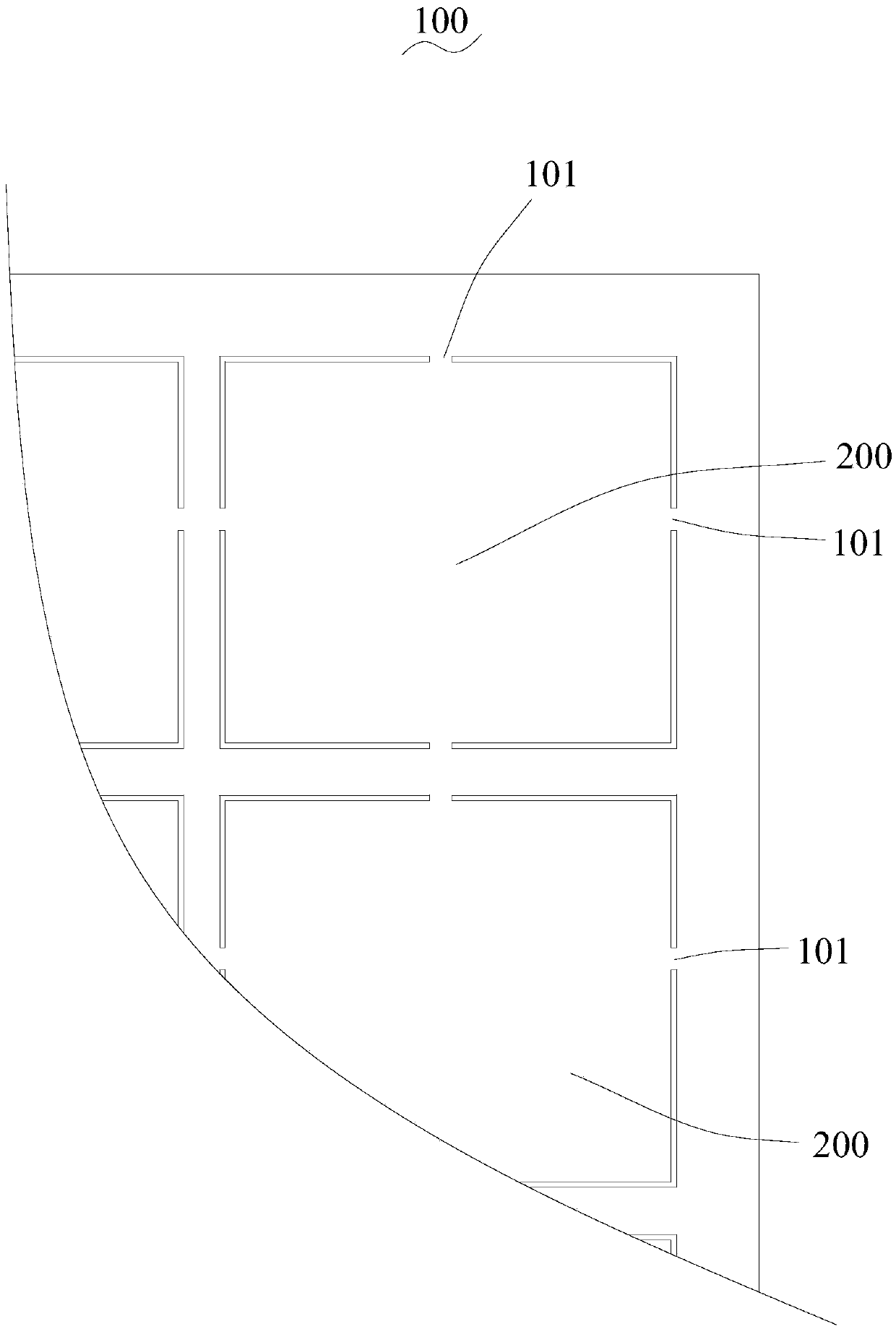
The invention provides a circuit board numerical control cutting process with no dowel needing to be nailed on a worktable and a numerical control machine. The numerical control cutting process comprises the following steps that a material board is positioned and fixed through a pneumatic chuck, wherein a first positioning pin column of the pneumatic chuck is a fixed pin column, and a second positioning pin column of the pneumatic chuck can move relative to the first positioning pin column to clamp and fix the material board; first time of numerical control cutting is conducted on the material board along the edge of a circuit board, a plurality of breaking positions are reserved between the circuit board and the material board and distributed at the circumferential edge of the circuit board at intervals, and the circuit board is connected with the material board through the breaking positions; second time of numerical control cutting is conducted on all the bearing positions through the numerical control machine to separate the circuit board from the material board, and the material board and the circuit board are simultaneously pressed on a worktable of the numerical control machine through a pressure foot device of the numerical control machine. By adoption of the technical scheme, the problems that in the prior art, in the circuit board numerical control cutting process, positioning and mounting procedures are tedious and positioning is difficult are solved.

Description

technical field [0001] The invention relates to the technical field of circuit board processing, in particular to a circuit board cutting process and a numerically controlled gong machine that do not require pinning on a workbench. Background technique [0002] Circuit board manufacturers process the shape of finished and semi-finished boards according to process requirements or customer needs. The traditional molding methods are organic gongs, beer boards, hand gongs, hand cutting and so on. CNC gong machines are widely used due to their safe operation, high efficiency and high forming precision. [0003] In the process of producing circuit boards, in order to improve efficiency and save costs, all small-area circuit boards are made on a large-area sheet, and then the small-area circuit boards are removed from the sheet by a CNC gong machine. cropped down. In order to avoid the relative displacement of the cut circuit board in the process of cutting the circuit board, wh...

Claims


Application Information

Patent Timeline
Patent Type & Authority Patents(China)
IPC IPC(8): B23D79/00B23Q3/08
CPCB23D79/00B23Q3/08B23Q2703/04
Inventor 黄任龙
Owner 雪龙数控设备(深圳)有限公司
Why Eureka
Eureka Blog
Learn More