Double-cycle desulphurization and dust removal device and flue gas desulphurization and dedusting method

A desulfurization and dust removal, double-circulation technology, which is applied in combination devices, separation devices, separation methods, etc., can solve the problems of failing to meet environmental protection standards, large footprint, poor flue gas treatment effect, etc. Turbulence, the effect of reducing overall volume and footprint

Inactive Publication Date: 2017-06-13
SHANGHAI LANKE PETROCHEM ENG & TECH
View PDF6 Cites 1 Cited by
  • Summary
  • Abstract
  • Description
  • Claims
  • Application Information

AI Technical Summary

Problems solved by technology

[0003] Chinese invention patent CN201510315376.6, the subject name is a dust removal and desulfurization co-processing device, the invention discloses that a first-level flue gas dedusting and desulfurization area, a second-level flue gas dedusting and desulfurization area and demisting are arranged in a tower according to the flue gas flow direction device, but the equipment for storing the reaction slurry in the secondary flue gas dedusting and desulfurization area is arranged outside the device, which occupies a large area. The desulfurization efficiency of this invention is 99%, and the dust removal efficiency is 75%, so it is suitable for those with higher sulfur content. The flue gas treatment effect is poor and cannot meet the environmental protection standard

Method used


Image

  • Double-cycle desulphurization and dust removal device and flue gas desulphurization and dedusting method

Examples


Embodiment 1

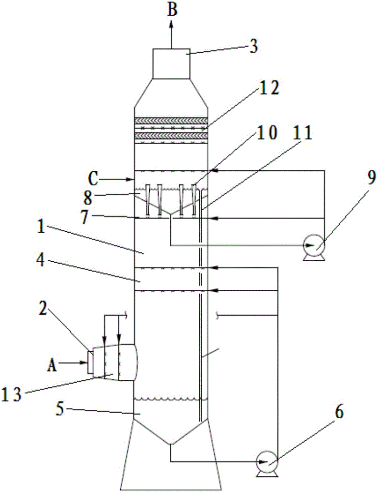
[0029] like figure 1 As shown, Embodiment 1 discloses a dual-cycle high-efficiency desulfurization and dust removal device, including: a tower body 1, including a flue gas inlet 2 arranged at the lower left of the tower body 1 and a flue gas outlet 3 arranged at the top of the tower body 1 The first-level spray layer 4 is arranged in the tower body 1 and above the flue gas inlet 2. In this embodiment, the first-level spray layer 4 includes two layers and one-level sub-spray layer; the first-level liquid storage bucket 5 , arranged in the tower body 1 and located below the primary spray layer 4, for collecting the primary spray circulating liquid; the quenching spray layer 13, arranged in the tower body 1 and close to the flue gas inlet 2, for cooling The flue gas entering from the flue gas inlet 2; the primary spray pump 6, its liquid inlet extends into the primary liquid storage bucket 5, and its liquid outlet is divided into two parts, one part is connected with the primary ...

Embodiment 2

[0034] Embodiment 2 discloses another specific embodiment of a double-cycle high-efficiency desulfurization and dust removal device. The double-cycle desulfurization and dust removal device and process conditions used in embodiment 2 and embodiment 1 are basically the same. The difference is that in this embodiment , the lye supplemented by the replenishment port of the first-level liquid storage bucket and the second-level liquid storage bucket is an aqueous lime solution, and the first-level spray layer is equipped with 5 layers of the first-level sub-spray layer, and the second-level circulation is equipped with 6 groups of Venturi tubes .

[0035] In this embodiment, lime aqueous solution is used as the first-level spray circulating fluid and the second-level spray circulating fluid to treat the flue gas. The desulfurization efficiency of this invention is 99.6%, the dust removal efficiency is 94.3%, and the sulfur content can be as high as 2%. The flue gas is treated to m...

Embodiment 3

[0037] Embodiment 3 discloses another specific embodiment of the dual-cycle high-efficiency desulfurization and dust removal device. The dual-cycle desulfurization and dust removal device and process conditions used in Embodiment 3 and Embodiment 1 are basically the same, except that the first-stage liquid storage bucket and The lye supplemented by the replenishment port of the secondary liquid storage bucket is ammonia solution, and the primary spray layer is equipped with 6 layers of primary sub-spray layers, and the secondary circulation is equipped with 8 sets of Venturi tubes.

[0038] In this embodiment, ammonia solution is used as the first-level spray circulation fluid and the second-level spray circulation fluid to treat the flue gas. The desulfurization efficiency of this invention is 99.7%, the dust removal efficiency is 94.5%, and the sulfur content can be as high as 2%. The flue gas is treated to meet the "ultra-clean emission" standard.

[0039] Combining Embodim...


PUM


Abstract

The invention discloses a double-cycle desulphurization and dust removal device and a flue gas desulphurization and dedusting method. The double-cycle desulphurization and dust removal device comprises a tower body with a flue gas inlet and a flue gas outlet, a first-stage spray layer positioned above the flue gas inlet, a first-stage liquid storage hopper positioned below the first-stage spray layer, a first-stage spray pump respectively connected to the first-stage liquid storage hopper and the first-stage spray layer, a second-stage spray layer positioned above the first-stage spray layer, a second-stage liquid storage hopper positioned above the first-stage spray layer, a second-stage spray pump respectively connected to the second-stage liquid storage hopper and the second-stage spray layer, and a Venturi tube arranged inside the second-stage liquid storage hopper. According to the flue gas desulphurization and dedusting method, flue gas undergoes first-stage spray to remove most pollutants in flue gas and then the flue gas undergoes second-stage spray to enhance the desulphurization and dedusting effect so as to meet the requirement of flue gas emission. The desulphurization and dust removal device of the invention has advantages of high integration level, small size, small floor space and high desulphurization and dedusting efficiency.

Description

technical field [0001] The invention relates to the field of flue gas desulfurization and dust removal process design, in particular to a double-cycle desulfurization and dust removal device and a flue gas desulfurization and dust removal method. Background technique [0002] With the promulgation and implementation of new environmental protection regulations, the control indicators for flue gas pollutant emissions are becoming more and more stringent. Generally, SO 2 Emission concentration is less than 100mg / m 3 , less than 50mg / m in key areas 3 , the particle emission concentration is lower than 50mg / m 3 , less than 20mg / m in key areas 3 . Even coal-fired power plants in some areas have begun to implement "ultra-clean emissions" (the emission concentrations of sulfur dioxide and particulate matter are not higher than 35mg / m 3 , 10mg / m 3 ). This requires the flue gas desulfurization and dust removal system to have very high desulfurization and dust removal efficiency...

Claims


Application Information

Patent Timeline
IPC IPC(8): B01D53/78B01D53/50B01D53/96B01D47/06B01D50/00
CPCB01D47/06B01D50/00B01D53/502B01D53/78B01D53/96B01D2247/10B01D2251/304B01D2251/604
Inventor 李少云马洪玺冒兰军张文军
Owner SHANGHAI LANKE PETROCHEM ENG & TECH
Why Eureka
Try Eureka