System and method for navigating minimally invasive surgery
A technology of minimally invasive surgery and navigation system, applied in the field of magnetic resonance, which can solve the problems of not developing imaging methods for special navigation system navigation
- Summary
- Abstract
- Description
- Claims
- Application Information
AI Technical Summary
Problems solved by technology
Method used
Image
Examples
Embodiment 1
[0114] Example 1 Fast local spin echo scanning
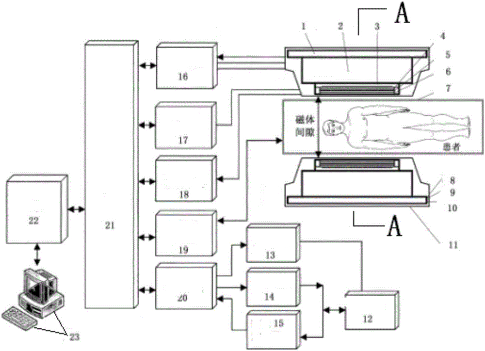
[0115] Based on the above MRI navigation system and navigation process, fast navigation sequence selection Figure 13 The local spin echo sequence Local-SE-NV shown, wherein the 90° RF pulse is preferably Figure 14 Minimum phase SLR pulses shown, two 180° refocused RF pulses optional Figure 15 The minimum phase SLR pulse shown or Figure 26 The linear phase SLR pulse shown. When the radio frequency power is insufficient, the radio frequency bandwidth can be reduced and the time-band product TBP can be kept unchanged, and the SLR pulse width can be adjusted accordingly, and the data point interval time of the waveform file can be adjusted according to the required SLR pulse width, and the gradient amplitude in the sequence parameter table can be adjusted at the same time until the desired layer thickness is obtained. In the case of metal artifact interference, the receiver bandwidth is preferably 100kHz or higher, the echo ...
Embodiment 2
[0118] Embodiment 2 Fast local multi-echo scanning
[0119] Based on the above MRI navigation system and navigation process, fast navigation sequence selection Figure 16 The local multiple gradient echo sequence Local-ME-NV shown, where the 90° RF pulse is preferably Figure 14 Minimum phase SLR pulses shown, first and second 180° refocused RF pulses selected Figure 15 The minimum phase SLR pulse shown or Figure 26 The linear phase SLR pulse shown. When the radio frequency power is insufficient, the radio frequency bandwidth can be reduced and the time-band product TBP can be kept unchanged, and the SLR pulse width can be adjusted accordingly, and the data point interval time of the waveform file can be adjusted according to the required SLR pulse width, and the gradient amplitude in the sequence parameter table can be adjusted at the same time to the desired layer thickness. In the case of metal artifact interference, the receiver bandwidth is preferably 100kHz or high...
Embodiment 3
[0127] Embodiment 3 Fast local three-layer synchronous scanning
[0128] Based on the above MRI navigation system and navigation process, fast navigation sequence selection Figure 18 Multilayer simultaneous excitation of the Local-MSME-NV sequence is shown. In order to increase the uniformity of RF excitation, the waveform of the first RF pulse of the imaging sequence adopts Figure 20 The linear-phase SLR pulse waveform is shown; and, in order to stimulate multiple layers of the body simultaneously, the RF pulse waveform is phase-encoded as follows:
[0129]
[0130] Here, SLR(t) denotes a linear phase SLR pulse, G s Indicates that the layer selection direction is The gradient strength of It is a vector representing the spatial position of the central layer, which can be set directly on the positioning image. Here, it is set as the isocenter. The position of the adjacent layer is set by the layer thickness THK and the layer distance ΔS in the layer selection directi...
PUM
 Abstract
Description
Claims
Application Information
 - Generate Ideas
- Intellectual Property
- Life Sciences
- Materials
- Tech Scout
- Unparalleled Data Quality
- Higher Quality Content
- 60% Fewer Hallucinations
Browse by: Latest US Patents, China's latest patents, Technical Efficacy Thesaurus, Application Domain, Technology Topic, Popular Technical Reports.
© 2025 PatSnap. All rights reserved.Legal|Privacy policy|Modern Slavery Act Transparency Statement|Sitemap|About US| Contact US: help@patsnap.com


