


Quick Research
Generate reliable direction feasibility study reports for your R&D in just a few steps.

Technical Q&A
Discover and master advanced knowledge NOW. Basics, ideas, possibilities, all at once.

Find Solutions
As an expert in R&D theories, this can generate solutions to your technical problems instantly.

Evaluate Feasibility
Analyze your overall solution with one click, know your potential R&D risks in advance.

Monitor Landscape
Get weekly tech updates, stay abreast of the latest tech innovations and key insights.
Voltage compensation method and circuit that eliminate the influence of DVR on adjacent load
A voltage compensation and load technology is applied in the field of voltage compensation methods and circuits to eliminate the influence of DVR on adjacent loads, and can solve problems such as the influence of adjacent loads.
- Summary
- Abstract
- Description
- Claims
- Application Information
AI Technical Summary
Problems solved by technology
Method used
Image


Examples
Embodiment 1
[0090] A voltage compensation method for eliminating the impact of DVR on adjacent loads, comprising the following steps:
[0091] Step 1: beta set calculate
[0092] For simplicity, determine β set The principle of size is consistent with the previous assumption. The equivalent impedance of the sensitive load and the non-sensitive load are the same, so the normal current of the sensitive load and the normal current of the adjacent non-sensitive load are equal in size and phase, and the normal current of the two can be set The amplitudes of both are 1; after the system voltage drops, the current amplitudes of both decrease to x 1 , the phase angle change value is β, and the phase shift makes β=β set ,satisfy The end point of falls exactly on an event current circle, such as Figure 7 As shown, at this time The amplitude is x 2 , then in and The phasor triangle of satisfies the law of cosines:
[0093]
[0094] remember exist and In the phasor triangle of...
Embodiment 2
[0117] As a voltage compensation device that provides a stable and reasonable voltage working environment for sensitive loads, DVR is generally used in medium and low voltage distribution networks, and medium and low voltage distribution networks are mostly three-phase four-wire systems. system, this technical solution uses three single-phase full-bridge structures as the simulation model. The energy storage device chooses a supercapacitor. Since it is a low-voltage distribution network, the voltage level is not high. The coupling type is relatively simple capacitive coupling, and the filter is composed of reactance and coupling capacitance.
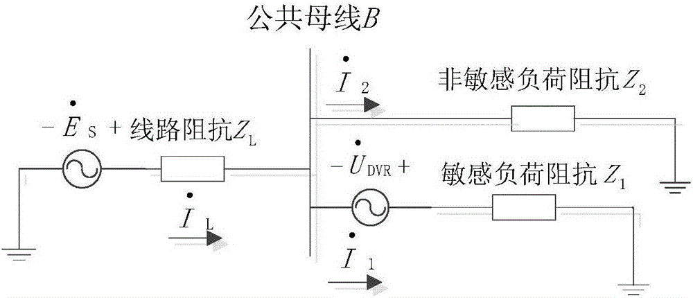
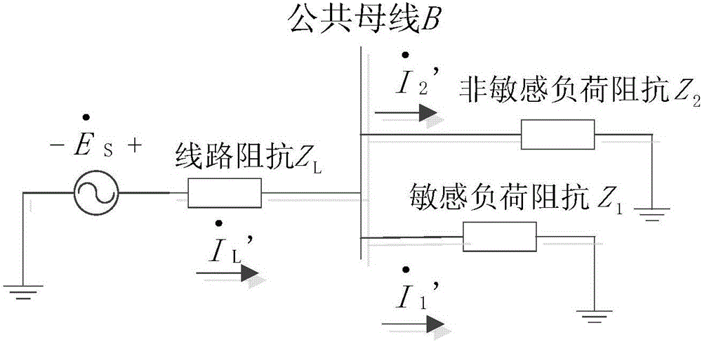
[0118] Assuming that the three-phase output voltages are independent of each other and do not interfere with each other, it is possible to simulate a single-phase DVR compensation circuit and analyze and study its corresponding compensation effect. Set up a distribution network terminal system, which consists of a single-phase power supp...
PUM
 Abstract
Description
Claims
Application Information
 - R&D Engineer
- R&D Manager
- IP Professional
- Industry Leading Data Capabilities
- Powerful AI technology
- Patent DNA Extraction
Browse by: Latest US Patents, China's latest patents, Technical Efficacy Thesaurus, Application Domain, Technology Topic, Popular Technical Reports.
© 2024 PatSnap. All rights reserved.Legal|Privacy policy|Modern Slavery Act Transparency Statement|Sitemap|About US| Contact US: help@patsnap.com