Pneumatic regulating valve used for mechanical manufacturing

A pneumatic regulating valve and mechanical manufacturing technology, which is applied in the field of mechanical parts manufacturing, can solve problems such as high noise, damage to the pneumatic regulating valve, and overall work imbalance, and achieve the effects of accurate flow characteristics, large working balance, and large allowable pressure difference

Inactive Publication Date: 2017-06-09
天津宗新机械配件有限公司
View PDF0 Cites 0 Cited by
  • Summary
  • Abstract
  • Description
  • Claims
  • Application Information

AI Technical Summary

Problems solved by technology

Because the temperature in the control valve in some specific occasions will be high and low, it is necessary to install the normal temperature type, high temperature type and low temperature type pneumatic control valve on the machine to be adjusted to adjust each other to complete the adjustment work, which is easy to adjust. Pneumatic regulating valve causes damage, and it is also prone to the phenomenon of unbalanced overall work, excessive pressure difference, inaccurate flow characteristics, and high noise

Method used


Image

  • Pneumatic regulating valve used for mechanical manufacturing
  • Pneumatic regulating valve used for mechanical manufacturing
  • Pneumatic regulating valve used for mechanical manufacturing

Examples


Embodiment 1

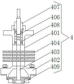
[0017] Embodiment one, refer to figure 2 : the spring pneumatic actuator 4 includes a valve tube 401 and a valve cover 402, the inside of the spring pneumatic actuator 4 is provided with a valve stem 403, and the valve stem 403 vertically runs through the valve tube 401 and the valve cover 402, the valve positioned above the valve cover 402 The inside of the pipe 401 is provided with a plurality of heat sinks 404 arranged at equal distances, and both ends of each heat sink 404 pass through the valve pipe 401 and extend to the outside of the valve pipe 401, and the valve stem 403 located above the heat sink 404 The surface is covered with a spring 406, and there is a gap between the spring 406 and the inner wall of the valve tube 401. A shaft seal 407 is arranged at the top of the gap, and a flexible graphite 408 is arranged in the gap. The valve stem 403 is in contact with the valve cover 402. The adjacent end is covered with a cylindrical guide sleeve 409 .

Embodiment 2

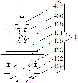
[0018] Embodiment two, refer to image 3 : The spring pneumatic actuator includes a valve tube 401 and a valve cover 402, the spring pneumatic actuator 4 is provided with a valve stem 403, and the valve stem 403 vertically runs through the valve tube 401 and the valve cover 402, and the valve located above the valve cover 402 The inside of the pipe 401 is provided with a plurality of heat shields 405, wherein the bottom heat shield 405 is the shortest, the middle heat shield 405 is the longest, and both ends of each heat shield 405 pass through the valve pipe 401 and extend to Outside the valve tube 401, a spring 406 is sheathed on the outer surface of the valve stem 403 above the heat shield 405, and there is a gap between the spring 406 and the inner wall of the valve tube 401, and a shaft seal 407 is arranged at the top of the gap , and flexible graphite 408 is arranged in the gap, and the end of the valve stem 403 close to the valve cover 402 is covered with a cylindrical ...


PUM


Abstract

The invention discloses a pneumatic regulating valve used for mechanical manufacturing, which comprises a valve body and a spring pneumatic actuator. A valve seat is fixedly arranged inside the valve body, and the valve seat is fixedly connected with a valve core with double sealing surfaces arranged on the top thereof. , and the valve body is fixedly connected with the spring pneumatic actuator set on its top. The spring pneumatic actuator includes a valve tube and a valve cover. A plurality of fins arranged equidistantly. The pneumatic control valve used in mechanical manufacturing adopts a cylindrical guide sleeve guide and a valve core with double sealing surfaces, and is equipped with a spring pneumatic actuator to ensure the overall work balance at normal temperature, high temperature and low temperature. And the allowable pressure difference is large, and has the advantages of accurate flow characteristics and low noise, and is suitable for occasions with large flow, large pressure difference between the front and back of the valve, and no leakage requirements.

Description

technical field [0001] The invention relates to the technical field of mechanical parts manufacturing, in particular to a pneumatic regulating valve for mechanical manufacturing. Background technique [0002] Control valve, also known as control valve, in the field of industrial automation process control, is the final control element that changes the process parameters such as medium flow, pressure, temperature, liquid level, etc. by means of power operation by receiving the control signal output by the adjustment control unit. It is generally composed of actuators and valves. According to the characteristics of the stroke, the regulating valve can be divided into straight stroke and angular stroke; according to the power used by the actuator, it can be divided into three types: pneumatic regulating valve, electric regulating valve and hydraulic regulating valve; according to its function and characteristics There are three types: linear characteristic, equal percentage ch...

Claims


Application Information

Patent Timeline
Patent Type & Authority Applications(China)
IPC IPC(8): F16K1/00F16K1/36F16K1/32F16K31/12
CPCF16K1/00F16K1/32F16K1/36F16K31/12
Inventor 马连新
Owner 天津宗新机械配件有限公司
Why Eureka
Try Eureka