Gear drilling machine

A drilling machine and gear technology, which is applied in the direction of boring/drilling, drilling/drilling equipment, boring machine/drilling machine parts, etc., can solve problems such as single function, poor use effect, and failure to meet the use requirements. To achieve the effect of protecting the environment

Inactive Publication Date: 2017-06-09
TAIZHOU LIHUA MACNINERY
View PDF0 Cites 0 Cited by
  • Summary
  • Abstract
  • Description
  • Claims
  • Application Information

AI Technical Summary

Problems solved by technology

The existing drilling machine for gears has simple structure, single function, poor use effect, and cannot meet the use requirements

Method used


Image

  • Gear drilling machine

Examples


Embodiment 1

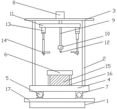
[0017] like figure 1 As shown, a gear drilling machine of the present invention includes a base 1, a fuselage 2 and an upper support frame 3. The base 1 is provided with two transverse guide rails, and the transverse guide rail 17 is provided with two longitudinal guide rails 7. The top of the longitudinal guide rail 7 is provided with a backing plate 4 for placing gears, the lower surface of the longitudinal guide rail 7 is provided with a roller 5 embedded in two transverse guide rails 17, and the lower surface of the backing plate 4 is provided with an embedded longitudinal guide rail 7 The inner roller 5, the backing plate 4 is provided with a clamp 6 for fixing the gear, the support frame 3 is provided with an oil cylinder 8, and the end of the piston shaft 9 of the oil cylinder 8 is equipped with a punch holder 10. The punch fixing frame 10 is fixed on the piston shaft 9 of the oil cylinder through the upper pressing plate 11, the punch fixing frame 10 is provided with a...


PUM


Abstract

The invention relates to a gear drilling machine. The technical solution adopted by the present invention is: a gear drilling machine, including a base, a fuselage and an upper support frame, two transverse guide rails are arranged on the base, two longitudinal guide rails are arranged on the transverse guide rail, and a For the backing plate where the gear is placed, the lower surface of the longitudinal guide rail is provided with rollers embedded in the two horizontal guide rails, the lower surface of the backing plate is provided with rollers embedded in the longitudinal guide rail, and the backing plate is provided with a clamp for fixing the gear, and a support frame There is an oil cylinder on the top, and the end of the piston shaft of the oil cylinder is installed with a punch fixing frame. The punch fixing frame is fixed on the piston shaft of the oil cylinder through the upper platen. There is a stopping device, which includes a hydraulic oil cylinder and a push plate arranged at the end of the piston rod of the hydraulic oil cylinder. The invention has the advantages of reasonable structure, which is beneficial to improve work efficiency and product quality.

Description

technical field [0001] The invention relates to a drilling machine, in particular to a gear drilling machine. Background technique [0002] Gear is a common mechanical transmission part, which plays an important role in the mechanical field. With the rapid development of the gear industry, the scale of the industry continues to expand, and the performance requirements for gears are also getting higher and higher. During gear processing, in order to reduce weight or increase processing standards, holes are generally drilled on the normal surface of the gear. The existing drilling machine for gears has simple structure, single function, bad use effect, and cannot meet the use requirements. Therefore, we need to find a new technology to solve this problem. Contents of the invention [0003] The object of the present invention is to provide a gear drilling machine with reasonable structure and good use effect in view of the above deficiencies. [0004] In order to achieve t...

Claims


Application Information

Patent Timeline
Patent Type & Authority Applications(China)
IPC IPC(8): B23B39/00B23B39/06B23B39/10B23B47/00
CPCB23B39/006B23B39/06B23B39/10B23B47/00
Inventor 马玉坤顾往林
Owner TAIZHOU LIHUA MACNINERY
Why Eureka
Try Eureka