
Flexible plate fixation of bone fractures

A bone plate and bone surface technology, applied in the field of elastically fixed bone plate, can solve problems such as implant fracture, hindering fracture healing, and delaying

Inactive Publication Date: 2017-05-31
ZIMMER INC
View PDF5 Cites 10 Cited by
  • Summary
  • Abstract
  • Description
  • Claims
  • Application Information

AI Technical Summary

Problems solved by technology

Therefore, an overly stiff locking plate structure may delay or prevent fracture healing, which may also lead to fracture of the implant or loss of screw fixation in the bone

Method used


Image

  • Flexible plate fixation of bone fractures
  • Flexible plate fixation of bone fractures
  • Flexible plate fixation of bone fractures

Examples


example 1

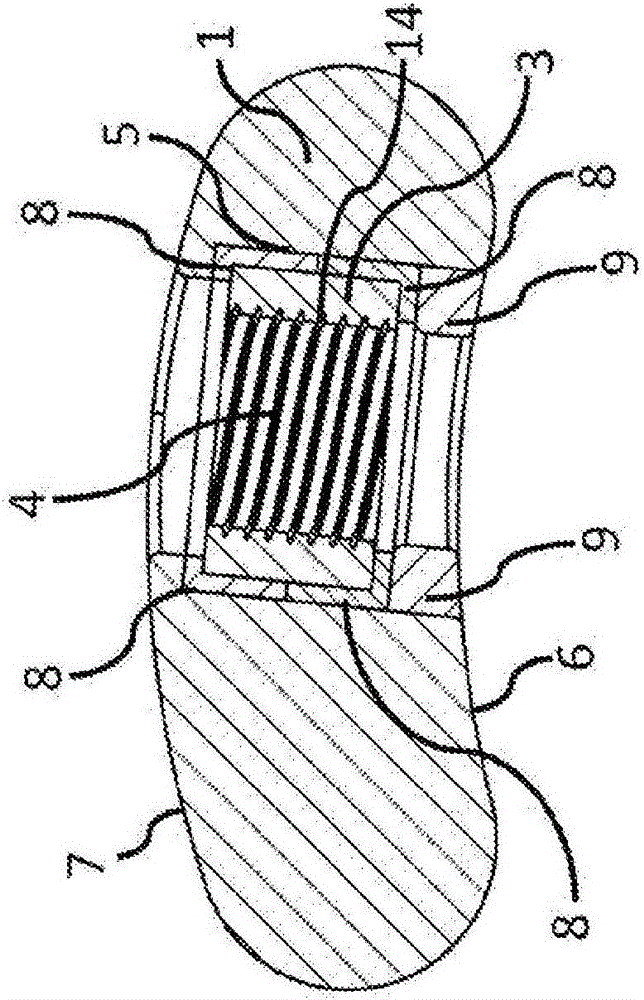
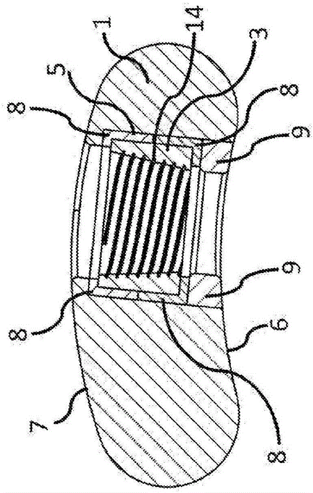
[0117] summary : The high stiffness of the locking plate structure can lead to iatrogenic fractures and implant fatigue. In contrast, impact damping resulting from elastic fixation is a major engineering strategy for improving the durability of load-bearing structures subjected to long-term dynamic loads. This example evaluates the impact damping provided by a "dynamic" locking plate design in which the locking screw holes are resiliently suspended within a silicone envelope on the inside of the locking plate.

[0118] In a biomechanical study, impact damping was evaluated against three different fixation structures applied to bridge the 10 mm fracture gap of the femoral shaft substitute: standard locking plate, dynamic locking plate and Ilizarov ring retainer. First, the three fixation structures were characterized by determining their axial stiffness. Subsequently, these structures were subjected to a series of axial shock loads to quantify the damping to force transmiss...

example 2

[0139] summary : Symmetrical axial dynamization of locking plate constructs using distal cortical locking ("FCL") screws was found to significantly increase the speed and strength of fracture healing. Because the FCL derives dynamization from flexure of the elastic screw shaft, it cannot be effectively scaled to the short screws required for fractures in small diameter bones. To address this scaling limitation, this biomechanical study evaluates a novel dynamic locking plate that derives a symmetric axial direction independent of the length of the locking screw by elastically suspending the locking hole within the plate being used. Motorized.

[0140] Standard locked (“standard”) plate configurations and dynamically locked (“dynamic”) plate configurations were examined in a diaphysis bridging plate model of the femoral shaft to determine the amount and symmetry of interfragmentary movement in response to axial loading, and in Evaluation of structural stiffness under axial l...


PUM

PropertyMeasurementUnit
Elastic modulusaaaaaaaaaa

Abstract

A device can be provided that includes a bone plate having an upper surface and a bone-facing surface, wherein the bone plate includes one or more openings extending through the bone plate from the upper surface to the bone-facing surface, and one or more sliding elements each including a fastener receiving hole. The one or more openings can at least partially surround a periphery of one of the receiving holes. Further, the one or more openings can be at least partially filled with an elastomer to support elastic suspension of the one or more sliding elements in the bone plate, thereby enabling relative displacement between the one or more sliding elements and the bone plate. At least one sensor can also be provided that is operable to assess a dynamic parameter of one of the one or more sliding elements within the bone plate.

Description

[0001] related application [0002] This application claims priority to US Provisional Patent Application 62 / 029,168, filed July 25, 2014, and entitled "FLEXIBLE PLATE FIXATION OFBONE FRACTURES." The foregoing disclosure is hereby incorporated by reference in its entirety. technical field [0003] The embodiments herein relate primarily to devices for fractured bone fixation. In particular, the present disclosure relates to a bone plate that provides elastic fixation of a fracture. This elastic fixation allows for small movements at the fracture site, thereby promoting natural fracture healing through the formation of callus tissue. Background technique [0004] Stabilized bone engaging plates for fractures are usually applied using bone screws. Traditionally, bone screws press the plate onto the surface of the bone to provide a stable fixation. More recently, locking plates have been introduced which typically have threaded receiving holes for positively and angularly s...

Claims


Application Information

Patent Timeline
IPC IPC(8): A61B17/80
CPCA61B17/80A61B17/8004A61B17/8047A61B17/8085A61B2017/00022
Inventor M·勃特朗S·M·马代K·沃茨S·蔡
Owner ZIMMER INC
Learn More