
Electromagnetic shielding and long-distance driver system for pulse radiation environment

A radiation environment, electromagnetic shielding technology, applied in the fields of magnetic/electric field shielding, electrical components, grounding circuits, etc., can solve problems such as distortion, and achieve the effects of large driving current, high bandwidth, and high input impedance

Inactive Publication Date: 2017-05-31
NORTHWEST INST OF NUCLEAR TECH
View PDF9 Cites 0 Cited by
  • Summary
  • Abstract
  • Description
  • Claims
  • Application Information

AI Technical Summary

Problems solved by technology

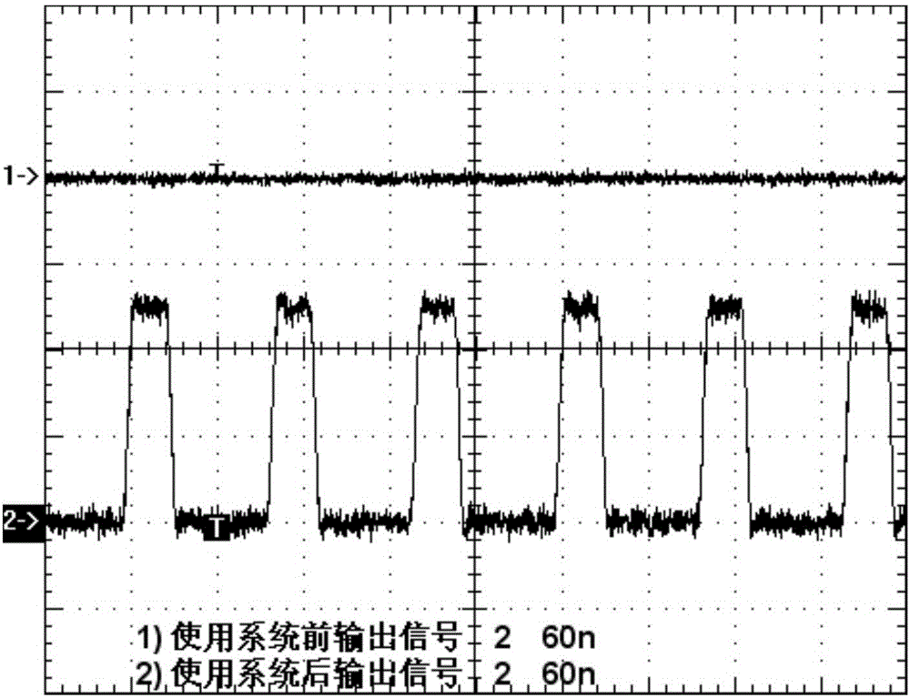
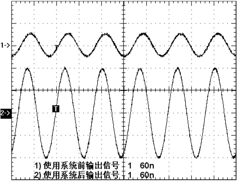
[0004] In order to overcome the problem of severe distortion when the signal is transmitted to the test terminal, the present invention solves this problem by adding the signal to the drive circuit near the input terminal. The method is to input a weak signal to a current amplifier circuit, and the circuit keeps the signal voltage constant. The driving current is amplified to drive a long cable, and then output through an impedance matching circuit, so that long-line driving can be realized with a fidelity signal waveform, and the output impedance matches the characteristic impedance of the cable to eliminate the problem of signal reflection

Method used


Image

  • Electromagnetic shielding and long-distance driver system for pulse radiation environment
  • Electromagnetic shielding and long-distance driver system for pulse radiation environment
  • Electromagnetic shielding and long-distance driver system for pulse radiation environment

Examples


Embodiment Construction

[0030] The present invention is further described below in conjunction with accompanying drawing:

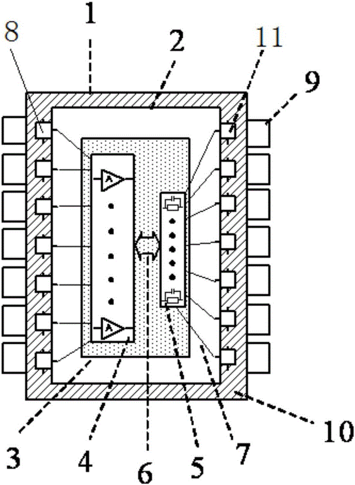
[0031] Such as figure 1 As shown, it is a structural schematic diagram of the present invention, an insulating material 10 is filled between the outer shielding shell 1 and the inner shielding shell 2, the current amplification circuit 4 and the impedance matching circuit 5 are welded on the PCB circuit board 3 and connected by a communication bus 6, the two circuits The coaxial cables 7 are respectively welded to the standard cable connector 8 of the input end and the standard cable connector 11 of the output end of the inner shielding shell 2, and the side connected to the current amplification circuit 4 is used as the system input end, and the impedance matching circuit 5 The connected side serves as the system output.

[0032] The outer shielding layer of the double-shielded cable for the external input signal is connected to the conductor hole 9, and the inner shielding la...


PUM

PropertyMeasurementUnit
Thicknessaaaaaaaaaa
Thicknessaaaaaaaaaa

Abstract

The invention provides an electromagnetic shielding and long-distance driver system for a pulse radiation environment. The electromagnetic shielding and long-distance driver system comprises two layers of shielding shells, wherein a shell body of the inner shielding shell is provided with multiple input end and output end standard cable connectors; a shell body of the outer shielding shell is provided with lead wire holes corresponding to the input end and output end standard cable connectors; the electromagnetic shielding and long-distance driver system further comprises a current amplification circuit and an impedance matching circuit which are located in the inner shielding shell; the input ends of the current amplification circuit are welded to the input end standard cable connectors; the output ends of the impedance matching circuit are welded to the output end standard cable connectors; signal input cables are connected with the input end standard cable connectors through the lead wire holes; signal output cables are connected with the output end standard cable connectors through the lead wire holes; the inner shielding shell is connected with a ground wire at the test end. By outer-layer shielding, electromagnetic pulse coupling current is eliminated; by inner-layer shielding, ground potential shaking is eliminated, and a stable reference ground potential is supplied; furthermore, the problem of serious distortion occurring during transmission of a signal to the test end is solved.

Description

technical field [0001] The invention relates to an electromagnetic shielding and long-line driving system, in particular to a weak-signal long-line driving and anti-electromagnetic interference system for the strong pulsed radiation field of an accelerator. Background technique [0002] The strong pulsed radiation field of the accelerator can produce strong electromagnetic radiation and ionizing radiation, so the distance between the signal measurement terminal and the accelerator target surface is required to be far enough to ensure the safety of the person and the measuring instrument. In the long distance, the signal transmission will have a large attenuation, especially for high-frequency signals or digital signals with weak driving ability, coupled with the coupling of strong electromagnetic pulses through cables, it is extremely difficult to accurately collect effective signals. Therefore, the accurate measurement of weak signals in the strong pulsed radiation field of...

Claims


Application Information

Patent Timeline
IPC IPC(8): H05H7/00H05H7/02H05K9/00
CPCH05H7/00H05H7/02H05K9/0064
Inventor 陈伟李瑞宾齐超杨善潮郭晓强
Owner NORTHWEST INST OF NUCLEAR TECH
Learn More