Moving Magnet Speaker
A loudspeaker and moving magnet technology, applied in the direction of sensors, loudspeakers, electrical components, etc., can solve the problems of difficult to improve the high-frequency transient response of moving-coil speakers, unable to meet performance requirements, and low high-frequency performance , to achieve the effect of improving the poor transient response of high frequency, enhancing the force and high sensitivity
- Summary
- Abstract
- Description
- Claims
- Application Information
AI Technical Summary
Problems solved by technology
Method used
Image
Examples
Embodiment 1
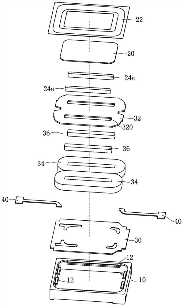
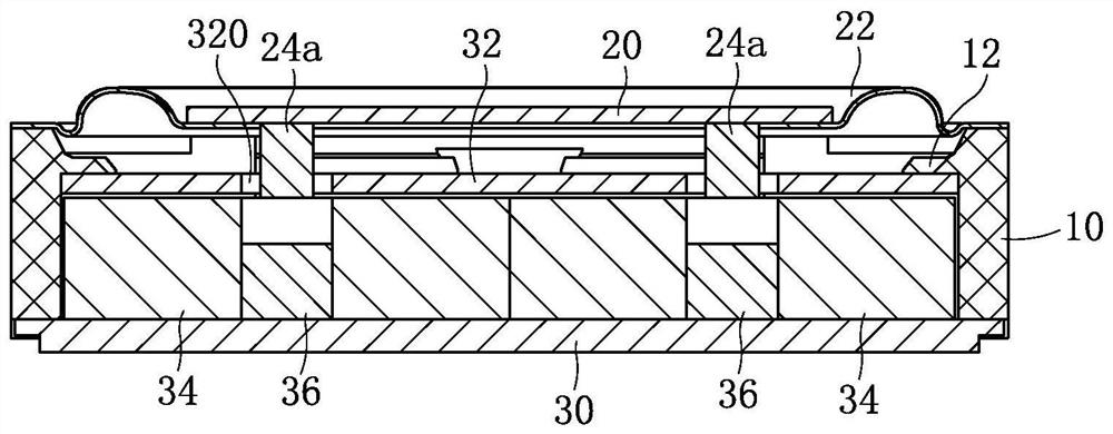
[0034] like figure 1 and figure 2 Commonly shown, a moving magnet loudspeaker has a rectangular parallelepiped structure and includes a rectangular annular casing 10 with openings at the upper and lower ends. The casing 10 accommodates a vibrating membrane and a voice coil 34 arranged in parallel with the vibrating membrane. A driving magnet 24a is fixed on the side of the vibrating membrane close to the voice coil 34; The force drives the diaphragm to vibrate and produce sound. In the present embodiment, the lower end surface of the casing 10 is combined with a plate-like structure basin frame 30 , the voice coil 34 is fixed on the position of the basin frame 30 located in the casing 10 , and an armature 36 is provided in the central hole of the voice coil 34 . 36 is also fixed to the basin frame 30. The diaphragm is arranged above the voice coil 34, and the diaphragm includes a folded ring 22 whose edge is fixed on the upper end face of the casing 10. The middle of the f...
Embodiment 2
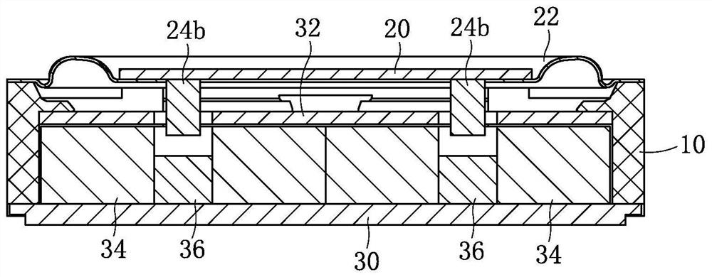
[0041] This embodiment is basically the same as the first embodiment, and the difference lies in:
[0042] like image 3 As shown, the height of the driving magnet 24b is larger, and its lower surface exceeds the upper surface of the voice coil 34, that is, the lower end of the driving magnet 24b is inserted into the central hole of the voice coil 34, and there is a gap between the driving magnet 24b and the armature 36. Vibration space.
Embodiment 3
[0044] This embodiment is basically the same as the first embodiment, and the difference lies in:
[0045] like Figure 4 As shown, the size of the driving magnet 24c is consistent with the size of the central hole of the voice coil 34, or the size of the driving magnet 24c is larger than the size of the central hole of the voice coil 34, the height of the driving magnet 24c is smaller than its width, it is a flat structure, In this embodiment, sufficient vibration space is required between the drive magnet 24c and the magnetically conductive member 32 .
[0046] like Figure 5 As shown, the working principle of the moving magnet speaker of the present invention is as follows:
[0047] Taking the moving magnet loudspeaker described in Embodiment 1 as an example, the vibration direction of the diaphragm is the vertical direction. In the figure, ⊙ and ⊕ represent the current direction in the voice coil 34, and ⊙ indicates that the current direction is perpendicular to the outs...
PUM
 Abstract
Description
Claims
Application Information
 - R&D
- Intellectual Property
- Life Sciences
- Materials
- Tech Scout
- Unparalleled Data Quality
- Higher Quality Content
- 60% Fewer Hallucinations
Browse by: Latest US Patents, China's latest patents, Technical Efficacy Thesaurus, Application Domain, Technology Topic, Popular Technical Reports.
© 2025 PatSnap. All rights reserved.Legal|Privacy policy|Modern Slavery Act Transparency Statement|Sitemap|About US| Contact US: help@patsnap.com


