A method and device for synchronous planning
A time synchronization, network element technology, applied in synchronization devices, data exchange through path configuration, digital transmission systems, etc., can solve problems such as error-prone, difficult, time-consuming, etc., to reduce workload, improve opening speed, The effect of improving planning accuracy
- Summary
- Abstract
- Description
- Claims
- Application Information
AI Technical Summary
Problems solved by technology
Method used
Image
Examples
Embodiment 1
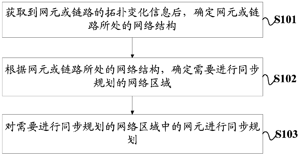
[0061] like figure 1 As shown, Embodiment 1 of the present invention provides a synchronous planning method, which specifically includes the following steps:
[0062] Step S101: After obtaining the topology change information of the network element or link, determine the network structure where the network element or link is located.
[0063] The topology change information mentioned here refers to change information such as deleting or adding or adjusting network elements or links in the synchronous network. Among them, the network structure includes: a ring structure and a chain structure. The so-called star structure can be regarded as a chain structure, and the network structure can be regarded as a combination of multiple ring structures. The topology change information includes network elements or chain structures. According to the identity information of the link, the network structure where the network element or link is located can be found out according to the ident...
Embodiment 2
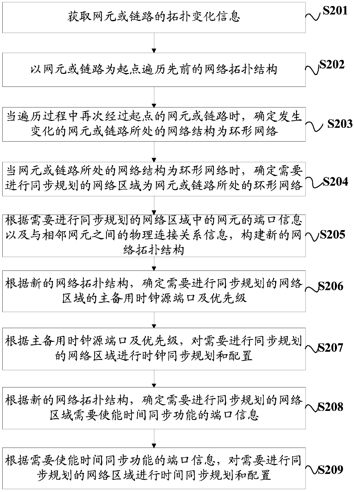
[0070] The first embodiment above briefly introduces the implementation of the synchronous planning method of the present invention, which will be further described below in conjunction with the accompanying drawings.
[0071] Specifically, such as figure 2 As shown, the synchronous planning method includes the following steps:
[0072] Step S201: Obtain topology change information of network elements or links.
[0073] Among them, there are many ways to obtain the topology change information of network elements or links, such as network element reporting or automatic acquisition. Taking network element reporting as an example, each network element in the synchronization network detects its own information in real time. When the physical connection relationship between adjacent network elements changes, it actively reports the topology change information. In this way, topology change information of network elements or links in the synchronous network can be automatically ob...
Embodiment 3
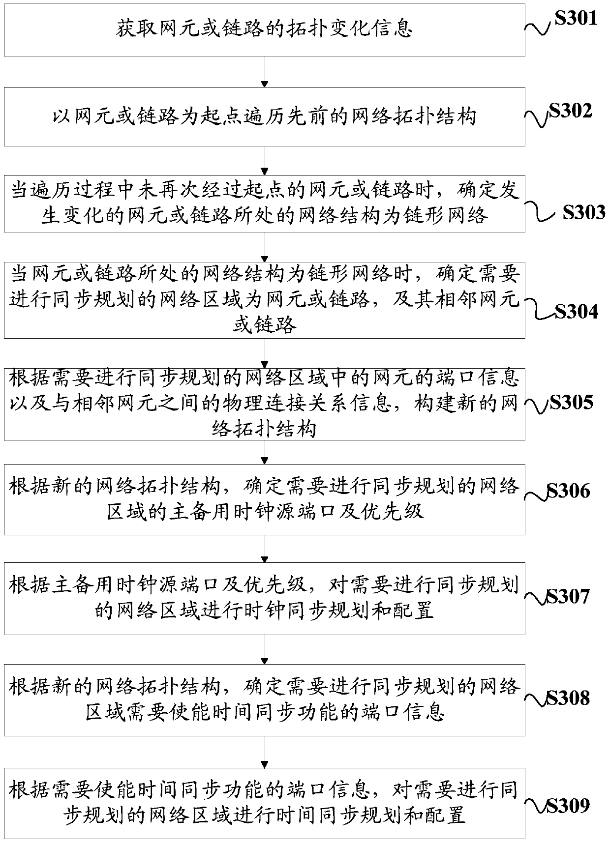
[0094] The second embodiment above introduces the synchronous planning method of the present invention in detail in combination with a ring link scenario, and will further explain it in combination with a chain link in the following.
[0095] Specifically, such as image 3 As shown, the synchronous planning method includes the following steps:
[0096] Step S301: Obtain topology change information of network elements or links.
[0097] Among them, there are many ways to obtain the topology change information of network elements or links, such as network element reporting or automatic acquisition. Taking network element reporting as an example, each network element in the synchronization network detects its own information in real time. When the physical connection relationship between adjacent network elements changes, it actively reports the topology change information. In this way, topology change information of network elements or links in the synchronous network can be a...
PUM
 Abstract
Description
Claims
Application Information
 - R&D
- Intellectual Property
- Life Sciences
- Materials
- Tech Scout
- Unparalleled Data Quality
- Higher Quality Content
- 60% Fewer Hallucinations
Browse by: Latest US Patents, China's latest patents, Technical Efficacy Thesaurus, Application Domain, Technology Topic, Popular Technical Reports.
© 2025 PatSnap. All rights reserved.Legal|Privacy policy|Modern Slavery Act Transparency Statement|Sitemap|About US| Contact US: help@patsnap.com


