Eureka AIR delivers breakthrough ideas for toughest innovation challenges, trusted by R&D personnel around the world.

Cast copper rotor of motor

A technology of electric motors and copper casting, which is applied to the rotating parts of the magnetic circuit, the shape/style/structure of the magnetic circuit, etc., can solve the problems of copper strips moving in the slot, copper strips moving, and hidden dangers of long-term operation of the motor, etc., to achieve Improvement of reliability and service life, effect of improving reliability

Inactive Publication Date: 2017-05-31
丁玉林
View PDF0 Cites 1 Cited by
  • Summary
  • Abstract
  • Description
  • Claims
  • Application Information

AI Technical Summary

Problems solved by technology

This structure requires a high degree of matching between the copper strip and the rotor slot, otherwise it will cause the copper strip to move in the slot, which will bring hidden dangers to the long-term operation of the motor. The reliability of this type of copper rotor is low.
In response to this problem, there is a copper rotor for electric motors on the market. The guide bar grooves in the rotor iron core formed by stacking the guide bar holes in the rotor punching sheets are spiral grooves, and the spiral copper guide bars are embedded in the guide bar grooves. The copper rotor of the motor with this structure reduces the movement of the copper bars in the slot, but there is still the phenomenon of the movement of the copper bars in the slot.

Method used


Image

  • Cast copper rotor of motor
  • Cast copper rotor of motor
  • Cast copper rotor of motor

Examples


Embodiment Construction

[0019] The present invention will be further described below according to the accompanying drawings and in conjunction with the embodiments.

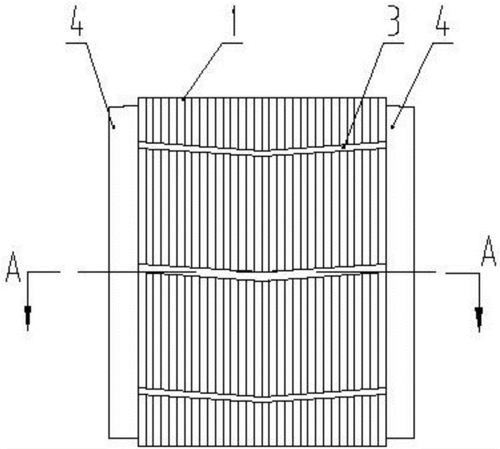
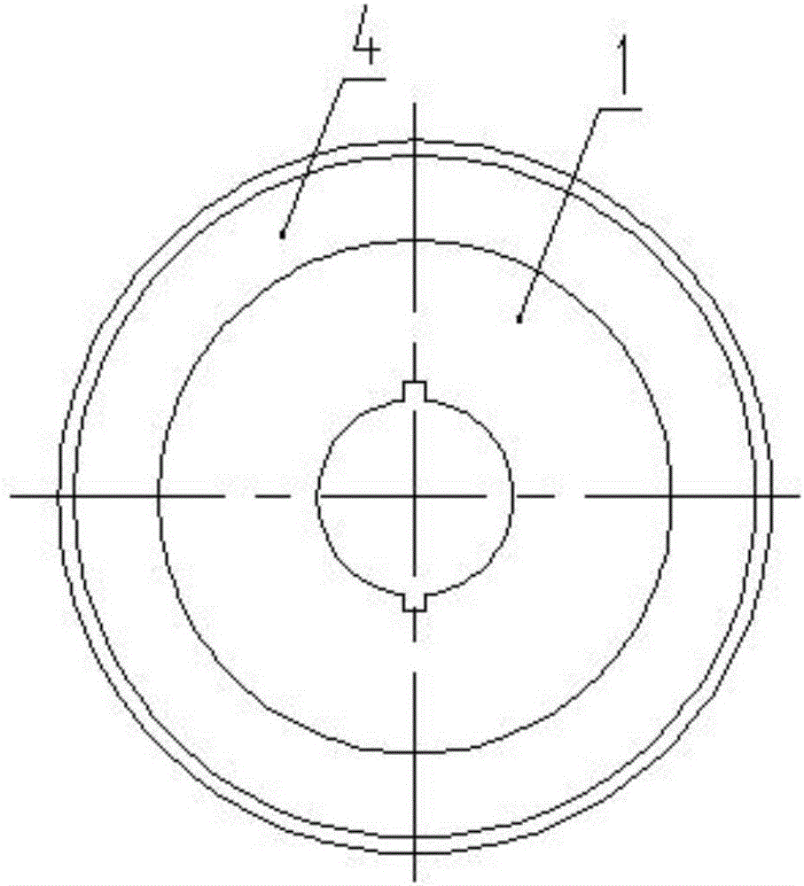
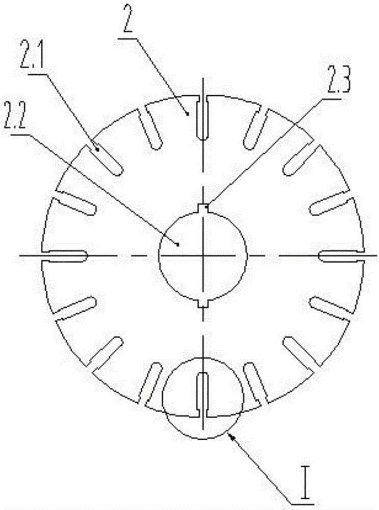
[0020] The cast copper rotor of the motor shown in the accompanying drawings includes a rotor core 1; the rotor core 1 is formed by laminating several rotor punches 2 of the same size and shape; the middle part of the rotor punch 2 is provided with shaft holes 2.2, which are evenly distributed There are several guide bar holes 2.1. In this embodiment, the orifices of the guide bar holes 2.1 around the rotor punching sheet 2 adopt a shrinking structure (the width of the opening is smaller than the inner width of the guide bar hole 2.1), and each rotor punching sheet 2 The guide bar holes 2.1 are stacked to form guide bar grooves in the rotor core 1; the inner wall of the rotor punch 2 shaft hole 2.2 is provided with a keyway 2.3, and in this embodiment, the inner wall of the rotor punch 2 shaft hole 2.2 is provided with a relative Rotor ...


PUM


Abstract

The invention discloses a cast copper rotor of a motor. The cast copper rotor comprises a rotor core, wherein the rotor core is laminated by a plurality of rotor sheets with the same size and shape; shaft holes are formed in the middles of the rotor sheets; a plurality of conducting bar holes are uniformly distributed around the rotor sheets; the conducting bar holes in the rotor sheets are laminated and then connected to form conducting bar grooves in the rotor core; key grooves are formed in inner walls of the shaft holes of the rotor sheets; copper conducting bars are arranged in the conducting bar grooves; copper end rings are arranged at the two ends of the rotor core, and fixedly connected with the two ends of the copper conducting bars; the conducting bar grooves are herringbone grooves; and the herringbone copper conducting bars are embedded into the conducting bar grooves. The cast copper rotor is further characterized in that the key grooves symmetrical to central axes of the shaft holes of the rotor sheets are formed in the inner walls of the shaft holes of the rotor sheets; the copper conducting bars are die-casted in the conducting bar grooves; the copper end rings at the two ends of the rotor core are die-casted and connected with the copper conducting bars; and openings of the conducting bar holes around the rotor sheets are in necking structures. The cast copper rotor can avoid displacement of copper bars in the conducting bar grooves, and is good in reliability.

Description

technical field [0001] The invention relates to a component of a motor, in particular to a copper rotor of a motor. Background technique [0002] In the existing copper rotor of an electric motor, after the copper bar is processed to a certain shape and size, the copper bar is extruded into the rotor core through an extrusion process to closely match the groove shape of the rotor, and the copper end ring and the copper bar are connected by welding. This structure requires a high degree of matching between the copper strip and the rotor slot, otherwise the copper strip will move in the slot, which will bring hidden dangers to the long-term operation of the motor, and the reliability of this type of copper rotor is low. In response to this problem, there is a copper rotor for electric motors on the market. The guide bar grooves in the rotor iron core formed by stacking the guide bar holes in the rotor punching sheets are spiral grooves, and the spiral copper guide bars are emb...

Claims


Application Information

Patent Timeline
Patent Type & Authority Applications(China)
IPC IPC(8): H02K1/22
CPCH02K1/22
Inventor 丁玉林
Owner 丁玉林
Why Eureka
Eureka Blog
Learn More