
Precharge time adjusting device, method, display driving circuit and display device

A technology of precharging time and adjusting device, applied in static indicators, instruments, etc., can solve the problems of screen brightness changes and poor flickering, and achieve the effect of reducing brightness and improving the phenomenon of poor flickering.

Active Publication Date: 2019-02-12
BOE TECH GRP CO LTD +1
View PDF7 Cites 0 Cited by
  • Summary
  • Abstract
  • Description
  • Claims
  • Application Information

AI Technical Summary

Problems solved by technology

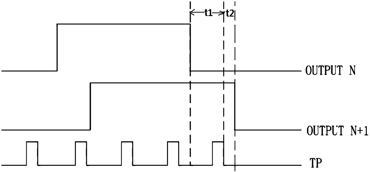
[0003] The main purpose of the present invention is to provide a pre-charging time adjustment device, method, display drive circuit and display device, which solves the problem that when two adjacent frames (or multiple frames) of pictures POL ( Polarity reversal) When the signal polarity is the same, the polarity of the data voltage will be the same, and the charging time will be different. The brightness of the two frames will change, which will lead to the problem of flickering.

Method used


Image

  • Precharge time adjusting device, method, display driving circuit and display device
  • Precharge time adjusting device, method, display driving circuit and display device
  • Precharge time adjusting device, method, display driving circuit and display device

Examples


specific Embodiment approach

[0057] According to a specific implementation manner, the modulation control signal may include a frequency modulation control signal; the modulation module may include a frequency modulation submodule;

[0058] The frequency modulation sub-module is connected with the control module, and is specifically used for controlling to reduce the frequency of the data latch control signal when receiving the frequency modulation control signal, so as to shorten the pre-charging time of the corresponding frame.

[0059] The frequency modulation sub-module may use a frequency modulator to shorten the pre-charging time of the corresponding frame by reducing the frequency of the TP signal.

Embodiment approach

[0060] According to another specific implementation manner, the modulation control signal may include a duty cycle adjustment control signal;

[0061] The modulation module may include a duty cycle adjustment submodule;

[0062] The duty cycle adjustment sub-module is connected to the control module, and is specifically used to shorten the corresponding frame by adjusting the duty cycle of the data latch control signal when the duty cycle adjustment control module is received. the precharge time.

[0063] According to another specific implementation manner, a POL polarity monitoring module can also be added inside the TCON (timing controller), that is, the polarity reversal signal judging unit 21 can be a POL polarity monitoring module arranged in the TCON, when the POL When the polarity monitoring module detects that the polarity of the POL signal of at least two consecutive frames is the same, it feeds back the corresponding information to the TCON MCU (Microcontroller Unit...


PUM


Abstract

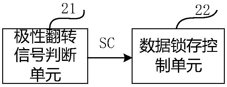
The invention provides a precharge time regulating device, a precharge time regulating method, a display drive circuit and a display device. The precharge time regulating device is applied to a liquid crystal display device, and comprises a polarity reversing signal judgment unit used for generating a precharge control signal when the polarity reversing signal judgment unit judges out that all continuous M frames of potential of an actual polarity reversing signal are at negative electrical level or all N frames of potential of the actual polarity reversing signal are at positive electrical level, and a data latching control unit which is connected with the polarity reversing signal judgment unit, and used for controlling shortening of precharge time of the corresponding frames by controlling change of waveform of a data latching signal when the data latching control unit receives the precharge control signal, wherein M and N are both positive integers larger than 1. The precharge time regulating device solves the problem of poor flicker phenomena in the prior art.

Description

technical field [0001] The present invention relates to the technical field of display driving, in particular to a precharging time adjusting device, method, display driving circuit and display device. Background technique [0002] At present, as LCD (Liquid Crystal Display, liquid crystal display) products are more and more widely used, the quality of various LCD products is valued by users, and the quality of display image quality has become the focus of attention of users. When the LCD panel is displaying a frame, the gate drive chip charges the data line, but the data of each frame will not be fully charged to saturation, and the POL (polarity inversion) signal can determine the polarity of the data voltage on the data line , but at certain time nodes, when the POL signal polarity of two adjacent frames (or multiple frames) is the same, the polarity of the data voltage will be the same, the charging time will be different, and the brightness of the two frames will be dif...

Claims


Application Information

Patent Timeline
Patent Type & Authority Patents(China)
IPC IPC(8): G09G3/36
CPCG09G3/3614
Inventor 梁利生许益祯肖利军刘志友白王静高少洪罗金佳冯文龙罗尧
Owner BOE TECH GRP CO LTD
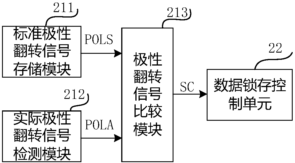
Learn More